*Please prepare a license ID and password for the license administrator.
*It is different from the service for JMAG WEB MEMBER (free membership). Please be careful.
Overview

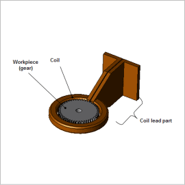
In order to ensure the abrasion resistance of teeth surfaces where teeth are in contact with each other, a gear must maintain the toughness of each entire tooth while increasing the hardness of the surface, necessitating making the teeth with tenacity. Inductive hardening, which is one of a number of surface hardening methods, can locally and rapidly heat and harden just the teeth surfaces.
In the induction hardening heating process, it is required to uniformly heat the surface of the gear. Also, to suppress oxidation, decarbonization, and deformation in the cooling process, it is necessary to complete the cooling in a short time. Therefore, the cooling rate is an important factor affecting the mechanical properties of the gear heated.
In order to accurately obtain the temperature change in the gear from induction heating analysis, it is necessary to not only accurately express the heat generated in the gear by electromagnetic induction, but also to obtain temperature distributions taking into account the change in temperature and physical characteristics due to heat generation. Because of this, electromagnetic field analysis – thermal analysis two-way coupled analysis is essential.
In this example, deals with induction heating and cooling analysis. An example is presented where the cooling rate for a gear differs depending on the cooling conditions.
Temperature Distribution of the Gear and the Change in Temperature vs. Time
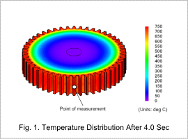
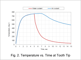
The temperature distribution of the gear at the end of the heating process is shown in Fig. 1, and the change in temperature vs. time at the tooth tip is shown in Fig. 2. From the temperature distribution, it can be seen that the tooth tip is generating heat due to eddy currents. Fig 2 shows the change in temperature at the tooth tip width center (point of measurement). It can be seen that water cooling is faster than air cooling so the effect from water cooling is higher.


Change Among the Gear Temperature Distributions in the Cooling Process

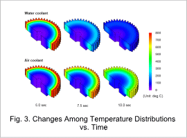
Fig. 3 shows the temperature distribution at various times in the cooling process. It can be seen that in the vicinity of the teeth tips significant cooling can be achieved with water cooling in a short time.
In addition, when comparing the temperature distribution between water cooling and air cooling, it can be seen that with water cooling the cooling of the teeth tips proceeds more quickly than the more interior portion of the gear. This is thought to be because the heat dissipation from the teeth tips in contact with the cooling water proceeds faster than the heat conduction interior to the gear.
In addition, when comparing the temperature distribution between water cooling and air cooling, it can be seen that with water cooling the cooling of the teeth tips proceeds more quickly than the more interior portion of the gear. This is thought to be because the heat dissipation from the teeth tips in contact with the cooling water proceeds faster than the heat conduction interior to the gear.


