Overview
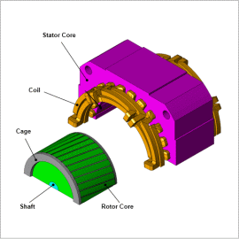
In order to correctly evaluate increases in temperature induction motor joule loss and iron loss, the use of coupled analyses is advantageous as so to obtain temperature distribution from thermal analyses using iron loss density distribution obtained from magnetic field analysis. This makes it possible to confirm overall temperature distribution and locations where temperatures grow particularly high.
In this example, evaluating induction motor temperature distribution.
Loss Density Distribution
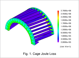
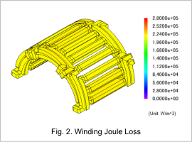
The joule loss density of the cage and windings is displayed in Fig. 1 and Fig. 2 respectively. A large portion of joule loss is distributed in the end ring.
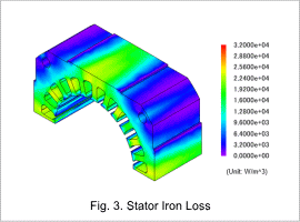
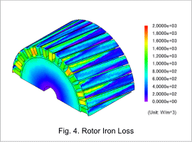
Iron loss analysis results for the stator and rotor are displayed in Fig. 3 and Fig. 4.
Temperature Distribution
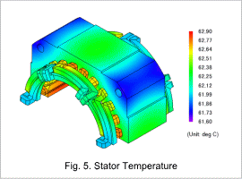
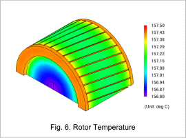
Stator temperature distribution is displayed in Fig. 5, and rotor temperature distribution is displayed in Fig. 6.
For the stator, each part is a heat source, and it is understood that temperatures rise until approximately 63 deg C. On the other hand, the main source of rotor heat is the cage, and it can be confirmed that heat is transferred to the rotor core. Because it is additionally difficult to emit the heat trapped within the stator, this becomes a high temperature of 156 deg C or above.
