Please enter your username and password to sign in.
* A JMAG Software User (paid user) account is required.
*It is different from the service for JMAG WEB MEMBER (free membership). Please be careful.
Overview
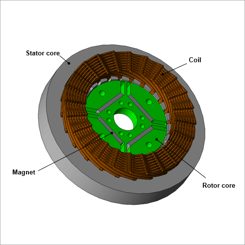
The main PM motor losses are the iron, magnet, and winding losses. Designers focus on the losses produced in the winding, especially those in the coil ends.
Winding losses refer to the DC as well as AC losses. Engineers can easily calculate DC losses manually according to the winding geometry and current. However, AC losses are difficult to estimate through simple calculations due to the influence of magnetic fields produced by adjacent conductors and various other phenomena. Engineers can create a prototype and use complex measurements for the coil to obtain AC losses but this is costly and takes time out of the design process.
This case study presents an analysis to obtain the AC losses of an IPM motor.
Winding losses refer to the DC as well as AC losses. Engineers can easily calculate DC losses manually according to the winding geometry and current. However, AC losses are difficult to estimate through simple calculations due to the influence of magnetic fields produced by adjacent conductors and various other phenomena. Engineers can create a prototype and use complex measurements for the coil to obtain AC losses but this is costly and takes time out of the design process.
This case study presents an analysis to obtain the AC losses of an IPM motor.
Loss Analysis
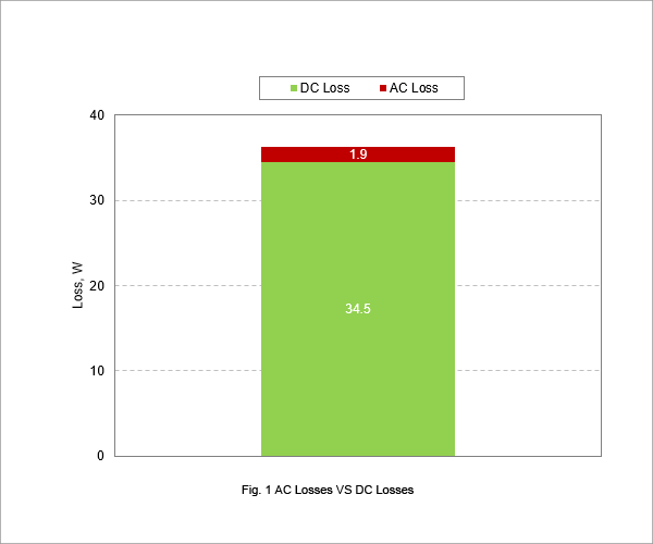
Fig. 1 illustrates the difference between the DC and AC losses.
A loss analysis that compares the DC and AC losses (total DC and AC losses) increases the losses roughly 5%.
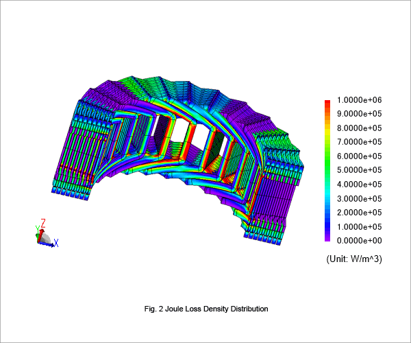
The AC losses in the coil ends outlined in Fig. 2 depend on winding geometry and leakage flux to the coil ends. The magnetic coupling between each conductor where eddy currents occur is primarily responsible for producing these losses.
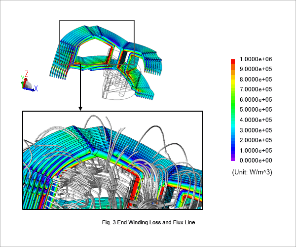
Fig. 3 presents the loss distribution and flux lines for the coil ends to identify the magnetic coupling between the stator ends and coil as well as the magnetic coupling between conductors. This magnetic coupling is the primary cause of the AC losses.