*Please prepare a license ID and password for the license administrator.
*It is different from the service for JMAG WEB MEMBER (free membership). Please be careful.
Overview

To control the position or speed of a motor or actuator, it is necessary to accurately detect the position of the mover and calculate command values based on that position. To detect the position, a method to detect leakage flux produced from an analysis target is widely used.
There are various detection methods, from using electromagnetic induction from a pickup coil to using the Hall effect or the magneto resistive effect. The latter methods have begun to be used in recent years because they can obtain a signal corresponding to the magnitude of the magnetic flux density regardless of the frequency.
To predict the signal produced in a sensor by the magnetic flux density generated at the sensor position and apply it to the displacement and speed control of the mover, electromagnetic field analysis that can accurately calculate the magnetic flux density and magnetic field distribution generated from the analysis target is useful.
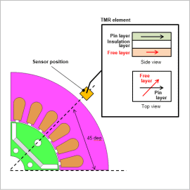
In this example, with the analysis target being a motor and the detection sensor being a TMR sensor, an example where a detection signal waveform is obtained that is based on magnetic field values computed from electromagnetic field analysis is presented.
Magnetic Field Radial Component at the Sensor Position

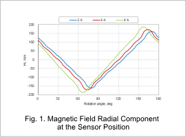
Fig. 1 shows the magnetic field strength radial component at the sensor position. Together with this value increasing as the motor current is increased, it can be confirmed that the rotor position achieving the maximum value shifts to a lower angle.
Resistance Change Rate of Each Sensor

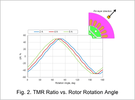
Fig. 2 shows the percentage change in resistance when the sensor pin layer is fixed in the radial direction, and the free layer magnetization direction is the same as the external magnetic field direction. The TMR ratio maximum value is 100 %, and the percentage change in resistance is for when the angle between the pin layer magnetization direction and the free layer magnetization direction is 90 deg.
When the current changes, it can be confirmed that the percentage change in resistance shifts to a lower rotation angle, and it can be seen that the relationship between the field strength and the position of the motor changes with the current amplitude. It can be seen that it is necessary to ascertain the relationship between the sensor output and the rotor position when the current changes in order to detect the rotor position accurately.
When the current changes, it can be confirmed that the percentage change in resistance shifts to a lower rotation angle, and it can be seen that the relationship between the field strength and the position of the motor changes with the current amplitude. It can be seen that it is necessary to ascertain the relationship between the sensor output and the rotor position when the current changes in order to detect the rotor position accurately.


