Overview
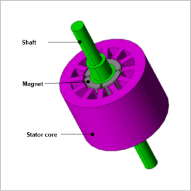
Performing optimization that uses FEA capable of analyses based on actual geometry can be effective in satisfying these requirements. Optimization results can be obtained with a high degree of freedom because topology optimization additionally performs searches that are not dependent on initial geometry.
In this document, the on / off method is used to search for stator teeth geometry that maximizes average torque and minimizes torque ripple with the entire areas of stator teeth tips as the design region.
Optimization Conditions
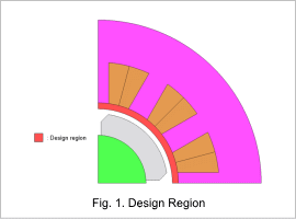
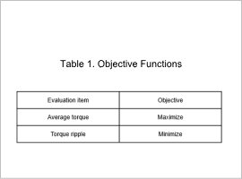
Fig. 1 shows the design region, and Table 1 shows the objective functions.
As shown in Fig. 1, the design region is the stator teeth parts, which are thought to have a large influence on torque and torque ripple.
Optimization Results
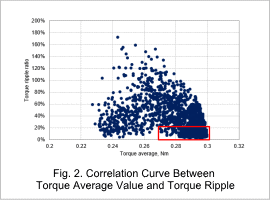
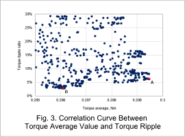
Fig. 2 shows a correlative diagram between the torque average value and torque ripple rate, and Fig. 3 shows a larger view of the range for the maximum torque and minimum torque ripple from Fig. 2. In Fig. 3, the maximum torque average value is shown at point A as the best case, and the minimum torque ripple rate is shown at point B.
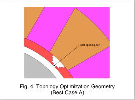
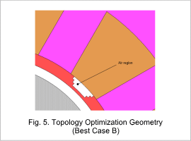
Topology optimization geometries for best cases A and B are shown in Fig. 4 and Fig. 5 respectively.
For best case A which has the maximum torque, material inside the teeth consists entirely of electromagnetic steel sheets. The presence of slot opening parts can also be observed here, whereas in best case B where torque ripple is at a minimum, teeth are connected around the entire arc, and there are no slot opening parts.
Sensitivity Analysis
As so to confirm the influence of teeth geometry on the torque characteristics, sensitivity analysis is performed for each best case.
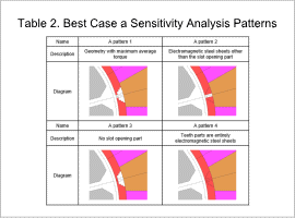
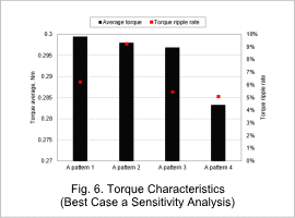
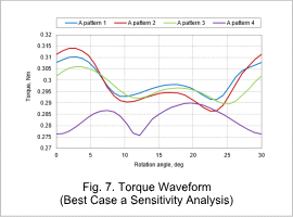
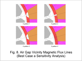
Consider best case A, which has maximum average torque. Analysis patterns are shown in Table 2, and analysis results are shown from Fig. 6 to Fig. 8. From a comparison between A pattern 1 and A pattern 3, it is understood that the presence or absence of slot opening parts has a small effect on torque characteristics. In A pattern 2, the end parts of the teeth tips are thick, and it can be considered that torque ripple increases because of the steep permeance with the slot opening parts. In A pattern 4, it can be considered that the average torque decreases because the magnet magnetic flux short-circuits at the teeth tip parts.
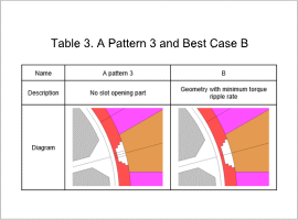
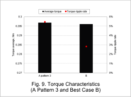
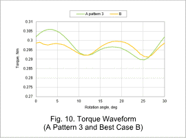
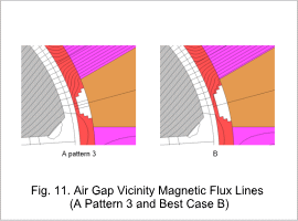
Consider best case B, which has the minimum torque ripple rate. Compare best case B and A pattern 3 which share similar geometry. Table 3 shows the geometry of A pattern 3 and best case B, and the analysis results are shown from Fig. 9 to Fig. 11. Because magnetic flux flows easier in the iron region for A pattern 3, the maximum torque increases. It can be considered that the reason the torque ripple rate increases is because the magnetic flux where force acts in the opposite direction of rotation flows easily.
