Overview
It is possible to run an analysis that takes into account the cooling and the heat resistance between the parts by using the thermal equivalent circuit.
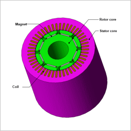
In this example, thermal equivalent circuit is used to run thermal analysis of a 3-phase IPM motor that accounts for cooling to the temperature change in the coil.
Cooling Specifications
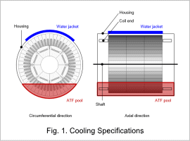
The water jacket is installed on the upper 90 deg sector of the stator.
Assume that oil in the ATF pool accumulates inside the lower 90 deg sector of stator.
Housing, coil end and shafts are modeled in the thermal equivalent circuit.
Thermal Equivalent Circuit
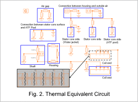
The sides of stator core are divided into three parts: the water jacket part, the ATFpool part, and the rest of the remaining parts, which are connected to the housing and outside air through thermal resistance component.
Core surfaces other than the above and coil ends are thermally connected to the shaft and the housing through the air inside the housing.
Temperature Change in Coil
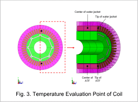
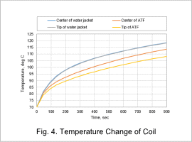
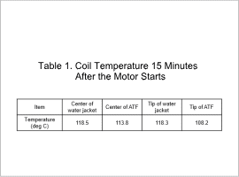
The temperature evaluation point of the coil is shown in Fig. 3, the temperature change of the coil is shown in Fig. 4, and the temperature 15 minutes after the motor starts is shown in Table 1.
You can determine whether the temperature is within the allowable temperature range of the heat resistance class by checking the coil temperature.
In this case study, the ATF pool part is cooler than the water jacket part when checking the temperature 15 minutes after the motor starts. You can see that the ATF has a higher cooling effect.
In the ATF pool part, the end portion is cooler than the central portion. You can see that cooling through the coil end is more effective than cooling through the core.
