Overview
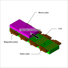
In order to obtain a large thrust force, the material’s nonlinear magnetic properties and the magnet’s demagnetization characteristics need to be accounted for, and in order to evaluate thrust force variations, they need to be analyzed after modeling a detailed geometry. This is why they need to be studied with a magnetic field analysis simulation based on the finite element method (FEM).
This note presents how to obtain cogging torque, a cause of thrust variation, and evaluate the thrust force and attraction force during drive.
Cogging
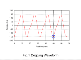
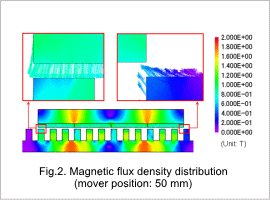
Fig. 1 shows the cogging force waveform. To examine the cause of the cogging force, the flux density distribution at the position (timing) circled in blue in fig. 1 is shown in fig. 2.
Fig. 2 shows that the flux density at the end of the mover is not evenly distributed. This imbalance of the magnetic circuit is the key factor that causes large cogging ripples.
Thrust and Attraction Forces
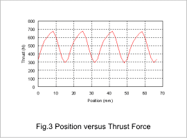
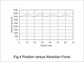
The position versus thrust force is shown in fig. 3, and the position versus attraction force is shown in fig. 4.
The graphs show that the periods of thrust and attraction forces have the same interval as the period of cogging force. The cogging ripple influences the thrust variations, so the cogging ripple needs to be made smaller in order to reduce the thrust variations. The attraction force is also the same as the radial force in a rotating machine, meaning that it is influenced by the magnetic flux flow in the gap, so it can be reduced by lessening the magnetic flux that flows perpindicular to the gap by using changes in the slot geometry.
