Overview
Optimizations using FEA can effectively reduce prototyping costs and labor. Parametric optimizations require experience and expertise to determine the design variables and range of dimensions. On the other hand, topology optimizations realize a drastically more design freedom by not relying on the initial geometry. Optimizations exploring the ideal magnet orientation direction, such as a Halbach array in SPM motors, are well known for increasing the average torque.
This case study runs an optimization to simultaneously explore the magnet topology and orientation directions through design variables to obtain at least the same torque as a Halbach array while minimizing torque ripple and magnet cross-section.
Base Geometry Using a Halbach Array
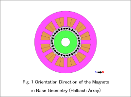
The base geometry has an average torque of 50.3 Nm, a torque ripple rate of 0.57, and a magnet cross-section for two poles with an area of 817 mm^2 .
Optimization Conditions
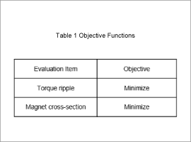
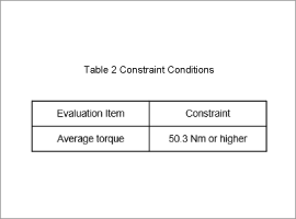
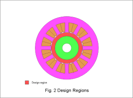
The objective functions are outlined in Table 1, the constraint conditions in Table 2, and the design regions in Fig. 2.
This case study uses the magnet geometry and orientation direction as design variables.
Optimization Results
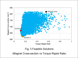
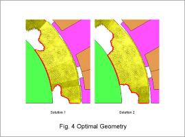
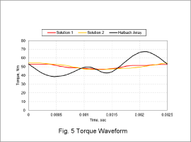
The scatter diagram in Fig. 3 illustrates the feasible solutions with the torque ripple rate on the horizontal axis and the magnet cross-section for two poles on the vertical axis. Solution 1 has the smallest torque ripple rate. Solution 2 has the smallest magnet cross-section for two poles. The results of the base geometry using a Halbach array are also provided in Fig. 1. Fig. 4 illustrates the magnet geometry and orientation direction for Solution 1 and Solution 2. Fig. 5 presents the torque ripple for Solution 1, Solution 2, and the base geometry using a Halbach array.
As shown in Fig. 3, the torque ripple rate is 0.11 for Solution 1, which is roughly one-fifth of the 0.57 torque ripple rate for the base geometry. Solution 2 has a magnet cross-section of 624 mm^2, which is 20% less than the 817 mm^2 in the base geometry.
The optimal solutions dramatically reduce torque ripple compared to the base geometry as shown by the torque waveform in Fig. 5.