*Please prepare a license ID and password for the license administrator.
*It is different from the service for JMAG WEB MEMBER (free membership). Please be careful.
Overview

The rotor’s rotation in a permanent magnet motor can generate positive and negative torque, even when there is no current flow. This torque is called “cogging torque.” While output torque a center of focus in motors used in precision equipment, cogging torque reduction must be taken into account as well. Skew and fractional slots are means of reducing this cogging torque. Skew is a widely used technique that attempts to cancel out cogging torque by applying an appropriate amount of twist to the stator or rotor. This generates electromagnetic force in the thrust direction, however, which presents challenges such as a decrease in performance and an increase in manufacturing cost. Fractional slots do not have the drawbacks found in skew, but the winding pattern is different from that found with integer slots. This means that the torque generation becomes difficult to evaluate because the teeth geometry and the magnet’s magnetization distribution are hard to design accurately.
In order to carry out these evaluations, an electromagnetic field analysis using the finite element method (FEM) needs to be carried out because it can perform detailed evaluations of the electromagnetic force distribution produced in the magnetic circuit.
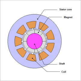
This Application Note presents the use of magnetic field analysis to obtain the cogging torque of an 8-pole, 9-slot SPM motor, which has relatively small period.
Cogging Torque Waveform

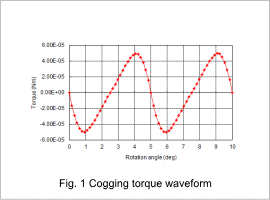
Fig. 1 shows the cogging torque waveform. As shown in the waveform, the amplitude is about 5e-5 Nm. The period of the cogging torque is also determined from the number of slots and poles, which in this analysis are 8 (poles) and 9 (slots). By dividing 360 deg by 72, the least common multiple of 8 and 9, one arrives at the period of cogging torque, which in this case is 5 deg.
Magnetic Flux Lines

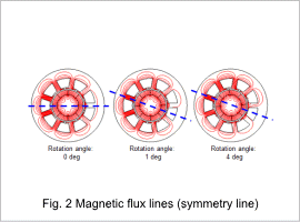
Fig. 2 shows the magnetic flux lines at rotation angles of 0 deg, 1 deg, and 4 deg. While the magnetic flux lines are symmetrical along a symmetry line at 0 deg, they are not symmetrical at 1 deg and 4 deg. This generates cogging torque.


