Overview
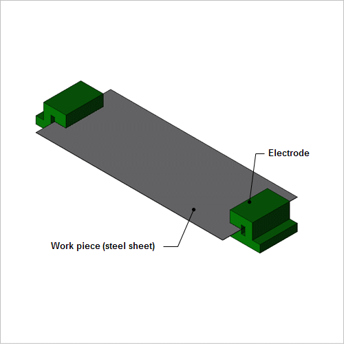
Unevenness in the current distribution flowing from the electrodes through the steel sheet is determined from the geometry and the material's electric conductivity. Electric conductivity changes according to the temperature, though, so both the electromagnetic phenomena and the heat transfer phenomena need to be analyzed at the same time.
This Application Note presents how to obtain the calculate current density distribution, Joule loss distribution and temperature distribution of steel sheet.
Current Density Distribution and Joule Loss Density Distribution
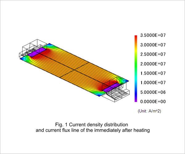
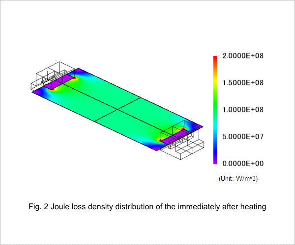
Fig. 1 shows the current density distribution and current flux line of the work piece immediately after heating. Fig. 2 shows the Joule loss density distribution of the work piece immediately after heating. The electrodes are shorter than the work piece in the width direction, so the current density is not uniform at the edges of the work piece, as can be seen in fig. 1. It is high near the tips of the electrodes and gets lower at the four corners of the work piece. Joule loss comes from electric resistance in the work piece, so its density has the same distribution as the current density. Their distribution is almost uniform near the center of the work piece. This joule loss becomes the heat source.
Temperature Distribution
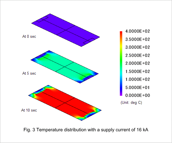
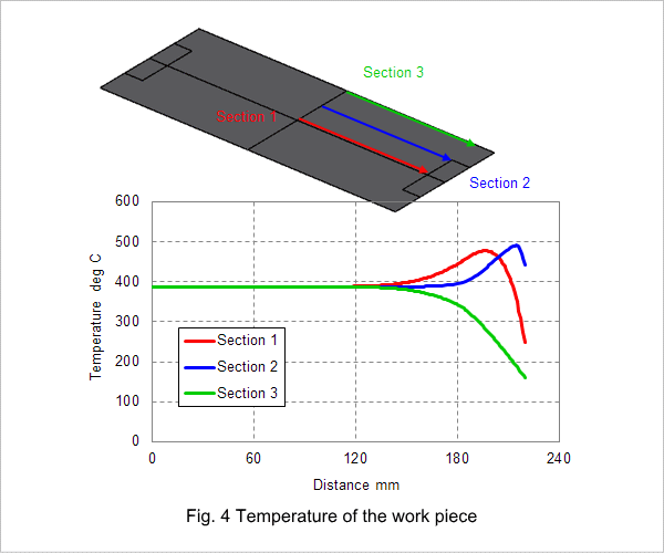
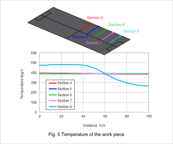
The work pieces temperature distribution is shown in fig. 3, and its work pieces temperature of 10 sec are shown in fig. 4 and fig. 5. Electric resistance generates heat in the work piece and heats it to about 400 deg C in 10 sec. The areas aside from the work piece's edges are heated uniformly.