Overview
![[JAC046] Sensitivity Analysis of the Magnetization Pattern of an SPM Motor](/images/catalog/e46-0.gif)
In order to control the magnetization pattern in the magnet of an actual machine precisely, a great number of magnetization devices is required. This makes a real machine hard to control, but with a magnetic field analysis simulation that uses the finite element method (FEM), it is possible to estimate how the cogging torque in the physical phenomenon will change by simply setting the magnetization pattern. Once the optimum magnetization pattern has been found, studying the magnetization method can lead to a reduction in development cost.
This Application Note presents the use of a magnetic field analysis to obtain the surface flux density for radial pattern, parallel anisotropic pattern, and polar anisotropy pattern magnets. It also displays the changes in induced voltage and cogging torque caused by differences in the magnetization patterns.
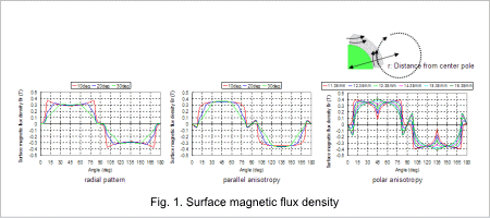
Surface Magnetic Flux Density

When the magnetization directions of the magnets are compared, the radial pattern is closest to a trapezoid, but the waveform of the parallel anisotropy pattern and polar anisotropy pattern are the closest to sinusoidal waves. The waveform of the induced voltage and the flux linkage can be calculated as being closer to a sinusoidal waveform for the parallel anisotropy and polar anisotropy patterns than the radial pattern.
Furthermore, the radial pattern and parallel anisotropy are closer to a sinusoidal waveform the larger the angle of the decay.
The waveform of the polar anisotropic pattern is closer to a sinusoidal waveform the larger the distance is from the center pole. However, the distance from the center pole is optimum at 15.35 mm because the waveform when r=16.35 has a higher magnetic flux density around 45 deg.
Induced Voltage, Flux Linkage,and Cogging Torque
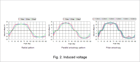
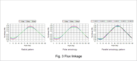
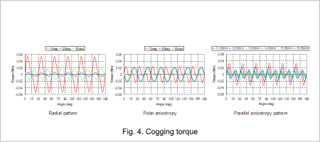
The induced voltage for the radial, parallel anisotropy, and polar anisotropy are indicated in 2, the flux linkage in 3, and the cogging torque in 4.
When the induced voltage waveform is compared for each pattern, the waveform for the radial pattern is closer to a trapezoid, while the waveforms for the parallel anisotropy and polar anisotropy patterns are closer to a sinusoidal waveform, just as predicted by the surface magnetic flux waveform. The waveforms for the flux linkage are also the same.
Furthermore, as can be seen from the surface magnetic flux density, when the angle of decay and the distance from the center pole are compared, the induced voltage waveform and flux linkage waveform are closer to a sinusoidal waveform the larger the angle of decay, or the larger the distance from the center pole.
Therefore, after comparing the magnetization patterns, the parallel anisotropy or polar anisotropy patterns have a smoother rotation that produces less cogging torque than the radial pattern. Furthermore, when comparing the angle of decay and the distance from the center pole, the cogging torque is the lowest with a radial pattern at 20 deg, a parallel anisotropy pattern at 30 deg, or for the polar anisotropy pattern, a distance when r= 16.35 mm.


