*Please prepare a license ID and password for the license administrator.
*It is different from the service for JMAG WEB MEMBER (free membership). Please be careful.
Overview

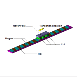
Linear motors have been widely used in carrier devices and the drive units of machine tools due to their capability for high acceleration and deceleration, as well as their accurate positioning. In order to improve performance people are trying to obtain a large thrust force in order to enhance responsiveness, but one also needs to fulfill the demand for the trade-off of reducing thrust force variations and the attraction force. There are also times when skew is added to the magnets because of requirements to reduce thrust force variation.
In order to obtain a large thrust force, the material’s nonlinear magnetic properties and the magnet’s demagnetization characteristics need to be accounted for, and they need to be analyzed after modeling a detailed geometry in order to evaluate thrust force variations. This is why the characteristics need to be studied with a magnetic field analysis simulation based on the finite element method (FEM).
This Analysis Note explains how to obtain the magnetic flux density distribution and cogging in a moving coil linear motor with skew applied to its magnets.
Magnetic Flux Density Distribution

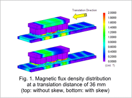
The magnetic flux density distribution at a translation distance of 36 mm is shown in fig. 1. Applying skew changes the magnetic circuit. It is anticipated that these changes in the magnetic circuit will affect the cogging torque.
Cogging Waveform

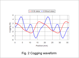
The cogging waveform is shown in fig. 2. When skew is applied, the cogging torque’s peak value falls by approximately 50%.


