Customers currently in the duration of their trial period will not be able to download model data.
Please provide the application note numbers that you wish to review for your distributor support team.
Please be aware that services differ from the free-to-register “JMAG-Express Online” and the “JMAG Technical Library”.
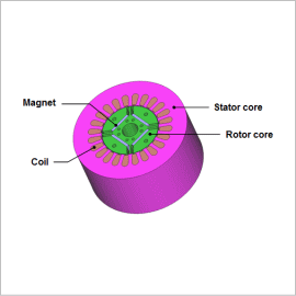
An IPM motor’s features are in its rotor geometry, where its magnets are embedded. When the stator’s rotating magnetic field is applied in a direction that runs perpendicular to the rotor magnets (the q-axis) the motor operates like a normal SPM motor. When the current phase is displaced and the d-axis component is applied, however, the motor operates so that the magnetic fields in the rotor magnets are weakened. This is called field weakening. In an SPM motor the d-axis current operates enough to weaken the magnetic field, so the rotation speed increases but the torque decreases. However, the rotor geometry in an IPM motor is created so that there is a difference in inductance between the d-axis and q-axis, so it is possible to generate torque with the d-axis current, which weakens the magnets. This makes it possible to recover the part weakened by the flux. Consequently, an IPM motor achieves a greater range of operation by incorporating field weakening controls.
For this reason an IPM motor’s characteristics depend greatly on its rotor geometry, so studies using the magnetic circuit method are difficult. In order to perform an advance design study accurately, an electromagnetic field analysis using the finite element method is necessary.
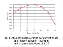
This Application Note presents the use of magnetic field analysis to obtain the efficiency of an IPM motor in each current phase with a rotation speed of 1800 rpm and the current amplitude of 4.0 A when the motor is driven by sinusoidal wave current.
Efficiency characteristics, loss by type, magnetic flux density distribution, the torque waveform
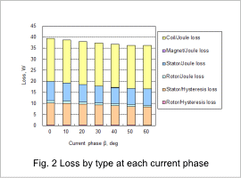
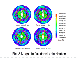
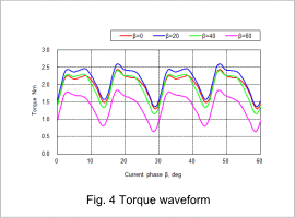
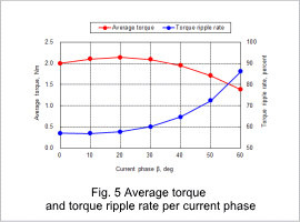
When the rotation speed is 1800 rpm and the current amplitude is 4.0 A, the efficiency characteristics per current phase are shown in fig. 1, the loss by type is shown in fig. 2, the magnetic flux density distribution is shown in fig. 3, the torque waveform is shown in fig. 4, and the average torque and torque ripple rate are shown in fig. 5. The results of the efficiency characteristics indicate that a maximum efficiency of 91% can be obtained at β = 30 deg. Adjusting the current phase can lower the magnetic flux density of the stator and reduce iron loss. Doing this, however, will reduce the average torque and increase torque ripple, which can lead to noise problems. This means that the current phase needs to be selected while accounting for the size of torque ripples in addition to the degree of efficiency.
Obtaining the efficiency by changing the rotation speed, current value, and current phase within the motor’s range of possible operation makes it possible to create an efficiency map.
This website uses cookies to improve functionality and performance. If you continue browsing the site, you are giving implied consent to the use of cookies on this website.
If you want to know more or refuse consent, read our Cookie Policy. Accept
Cookies Policy
Privacy Overview
This website uses cookies to improve your experience while you navigate through the website. Out of these cookies, the cookies that are categorized as necessary are stored on your browser as they are as essential for the working of basic functionalities of the website. We also use third-party cookies that help us analyze and understand how you use this website. These cookies will be stored in your browser only with your consent. You also have the option to opt-out of these cookies. But opting out of some of these cookies may have an effect on your browsing experience.
Necessary cookies are absolutely essential for the website to function properly. This category only includes cookies that ensures basic functionalities and security features of the website. These cookies do not store any personal information.