*Please prepare a license ID and password for the license administrator.
*It is different from the service for JMAG WEB MEMBER (free membership). Please be careful.
Overview
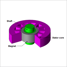
Reductions in vibration and noise are being sought after because they are a cause of torque variations in motors, and demands for reduction are particularly strong with motors that are used in machine tools and power steering. Cogging torque, which is a torque variation that is produced when there is no current, is generated because the electromagnetic force produced in the gap changes according to the rotor’s rotation. This makes it necessary to apply skew to the stator and rotor and come up with innovative geometry for the magnet and stator in order to reduce torque variations by limiting variations in the electromagnetic force. Applying skew reduces the cogging torque, but it also brings disadvantages such as producing force in the thrust direction and generating eddy currents from the magnetic flux that links in the lamination direction.
Consequently, in order to accurately evaluate a motor that has skew applied, one needs a magnetic field analysis simulation that uses the finite element method (FEM), which can account for a detailed 3D geometry, instead of studies that use the magnetic circuit method or a 2D magnetic field analysis.
This Application Note presents the use of a magnetic field analysis to obtain the flux density distribution, cogging torque, and induced voltage of an SPM motor that has skewed magnetization applied to its magnet.
Magnetic Flux Density Distribution
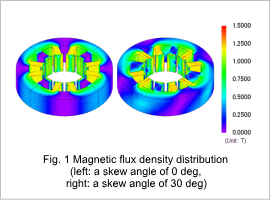
Fig. 1 shows the magnetic flux density distribution at the rotation angle of 90 deg. From fig. 1, it is apparent that the magnetic circuit changes when the magnet is skewed. These variations in the magnetic circuit have an effect on the cogging torque waveform.
Cogging Torque Waveform
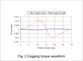
Fig. 2 shows cogging torque waveforms at skew angles of 0 deg and 30 deg.
The peak value of the cogging torque is reduced by approximately 90% when skew has been applied to the magnet.
The peak value of the cogging torque is reduced by approximately 90% when skew has been applied to the magnet.
Induced Voltage Waveform
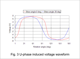
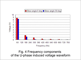
The induced voltage waveforms of the U-phase at skew angles of 0 deg and 30 deg are shown in fig. 3, and the frequency components of the U-phase’s induced voltage waveforms are shown in fig. 4.
The high frequency components are reduced when skew is applied to the magnet. The ratio taken up by the fundamental frequency of 60 Hz out of the total frequency components is 71% with a skew angle of 0 deg and 82% with a skew angle of 30 deg. According to these results, the induced voltage waveform is smoother at a skew angle of 30 deg than at an angle of 0 deg.
