Overview

Finite element method (FEM) analysis is useful for accurately estimating inductance over a wide current range, while also accounting for the effects of the gap’s inductance and nonlinearity in magnetization properties, and applying this during design.
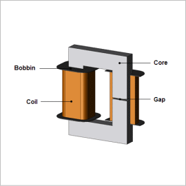
This Application Note presents how to obtain a high-current reactor’s superimposed direct current characteristics when the gap length is varied.
Superimposed Direct Current Characteristics
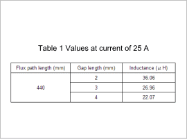
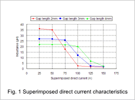
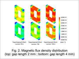
The relationship between the length of the flux path, the gap length, and the inductance when the direct current is 25 A is indicated in table 1, the superimposed direct current characteristics are indicated in fig. 1, and the magnetic flux density distribution is indicated in fig. 2.
From table 1, it is apparent that the inductance decreases as the gap length becomes larger. This is because the magnetic resistance of the entire magnetic circuit is made up of the magnetic resistances in the core and the gap connected in series, and the magnetic resistance of the gap increases with gap length. From fig. 1, it can be seen that the direct current at which the inductance starts decreasing is smaller with a shorter gap. This is because the core becomes magnetically saturated more easily as the gap becomes shorter, as shown in fig. 2.


