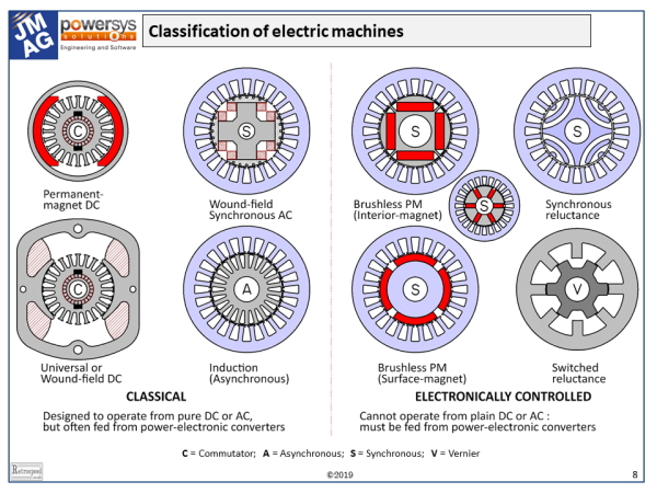
The diagram shows most of the electric machines in common use, together with the two reluctance machines which are rare but interesting. Classification is much more than an academic exercise: it reflects the organization of the electric machinery industry and all its applications and markets. The diagram is “tuned” for the modern era, with plenty to guide us into the future. It is also valid for at least the last 40 to 50 years. If we go back before that, the electronically controlled machines on the right would largely disappear, and there would be more classical machines such as rotary converters, repulsion motors, specialty traction motors, and many others which are practically extinct.
The classical machines all date back to the late 19th century (yes, the Meiji era!), and they are all still with us today, often with power-electronic controllers. But since about 1970 the modern electronically-controlled machines have become widespread, boosted enormously by the development of permanent-magnet materials. At the same time the demand for higher efficiency and the expansion in the range of electrically-powered tools and appliances has increased the market for these machines. For many years the reluctance machines have been kept on the sidelines by the superlative performance of PM machines, but their roles could grow in future if magnets become scarce.
The number of poles is possibly the most important design parameter in any machine. It is the starting-point of the mechanical configuration and the layout of the windings. To understand its role correctly, it is desirable to classify the machines even further into four main groups : C (commutator machines), A (asynchronous AC machines or induction machines); S (AC synchronous machines); and V (vernier machines). These classification letters have been “stamped” on the shafts in the diagram! Every machine has a rotor and a stator, and it may not be possible to count the number of poles simply by examining one or the other.
The simplest case is that of the AC synchronous machine S, where the number of poles is defined by the number of magnet poles (or wound-field poles); these are generally easy to recognize as clearly defined mechanical features. The synchronous reluctance motor also has an obvious pole-count in terms of flux-barriers (or groups of flux-barriers) on the rotor.
If we examine the stator of any AC machine, we can often determine the number of poles by a careful examination of the winding layout. We have to understand the distinction between phases, and we have to be careful to note the spans and polarities of the coils. When the coil-span is greater than 1 slot-pitch, it is usually quite close to the pole-pitch, and from this we can deduce the number of poles. But when the coil-span is 1 slot-pitch, as in single-tooth windings, the number of poles may not be obvious because of the fractional number of slots/pole. For example, the same 12-slot stator can be used with 8, 10, or 14 poles, and we cannot infer the pole-number from the coil-span. In such cases we need to understand the relationship between the working harmonic and the winding layout.
Of course the numbers of stator poles and rotor poles must be identical, and in the synchronous machine it determines the speed when the supply frequency is given. However, in fractional-slot machines the stator winding will often produce subharmonic components of the ampere-conductor distribution, which must not be confused with the working harmonic that corresponds to the number of rotor poles.
In the asynchronous cage-type induction machine A the number of rotor poles cannot be observed on the physical rotor, because the poles are induced by electromagnetic induction when the machine is running. In the wound-rotor type of induction machine we may be able to determine the number of poles by examining the winding, and the coil-spans in particular, but we have to be careful because all the windings are shorted together at some point.
In the changing modern world of electric vehicles and exotic technology, it is easy to focus on AC machines (and especially PM machines), and overlook the other types. At the left-hand side of the diagram, commutator machines C are still common (PM types in automotive auxiliaries, AC types in applicances and power tools, and wound-field DC in rail traction and some large drive systems). Here the number of poles can usually be counted directly on the field structure (magnets or coils); but much less easily on the armatures, where the only indirect clue may be the coil-span.
Lastly the switched reluctance machine on the right-hand side is a vernier-type machine (V), in which there appear to be different numbers of physical stator and rotor poles. Essentially the poles are excited intermittently in groups, in such a way as to establish a pulsed magnetic field with a certain number of magnetic poles that is not equal to either the number of stator poles or the number of rotor poles. To determine the number of working magnetic field poles requires a proper understanding of the theory of the switched reluctance motor. It’s not difficult, but it is certainly unfamiliar to anyone steeped in the design of conventional AC or DC machines.
The family of AC drives is identified by the blue shading in the diagram, and we can see the extraordinary scope of common features covering a huge proportion of the machines that are of key importance today. These machines all share the same stator topology (including windings), and they are all fed from AC inverters, usually PWM inverters with controlled instantaneous current, which gives rapid dynamic response and high efficiency. With relatively minor variations, most of them also use field-oriented control principles (vector control), so that there is a high degree of commonality in components, infrastructure, and know-how. This commonality helps to reduce the effective cost of AC drive products, but it does not extend to machines outside the family.
Unified theory — Over the years we have seen some heroic attempts to generate a unified theory or generalized theory of electric machines. Personally I believe that complete unification is a “wild goose chase”, while we must recognize that certain elements of generalized theory are vitally important (and used every day by control engineers as well as machine designers). The dq-axis paradigm is an example. It has practical embodiments in the separate fields of DC and AC machine design. In AC machine design it was introduced by Blondel in the early 1890s and used daily in design offices for 35 years before Park’s transform, which is much more mathematical and closely aligned with unified theory. Blondel’s version is still current, and I would say, more compatible with modern finite-element methods. But trying to combine and unify the AC and DC machine design theories can be confusing and maybe not of much practical use, even though both of them clearly rest on their separate dq axes.
As another example, the matrix methods taught by Gabriel Kron for the assembly and analysis of windings are elegant, powerful, and perfectly suited for computer methods; but where he ascends into tensors and other aspects of generalized theory, the simplifying assumptions multiply, and the practical value to the machine designer becomes limited.
Today we might be tempted to contemplate an extension of the generalized theory, in terms of the question, Does the finite-element method unify the theory of electric machines? I would say not. It extracts the physics and is not terribly concerned about the engineering theory. This is not unkind! We need the physics and we need to be good at analysis. But the design of machines — why they are the way they are — doesn’t come from the finite-element method or any other software tool. It comes from the individual and highly-developed theories of the separate machine types, and the imagination of the designer. Even though there is common ground between these things, complete unification is (I would say) a “wild goose-chase”, a chimera. The machines in the chart are destined to keep their places.
Related article
Use this form to send us your comments. Your valuable feedback will be used for future reference.
Please note that we will not answer any questions. Thank you in advance for your understanding.
Caution: This entry form is for English only. Please refrain from using multibyte characters such as Japanese, Chinese, and Korean.

