We often hear the terms “salient-pole” or “non-salient-pole” in relation to electric machines. “Saliency” is the idea of “projecting beyond the general outline”, and it refers to the poles in an electric machine which project or “stand out” from the otherwise-smooth circle of the stator or rotor surface. For the purposes of this article, a surface which has no saliency will be called round. A round member may be slotted, but the effects of slotting are considered to be negligible in this discussion.
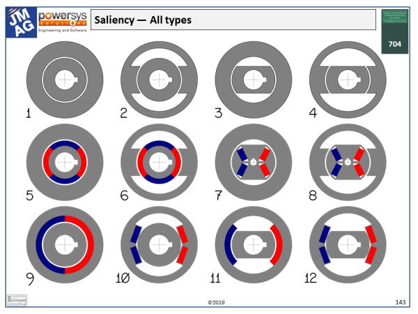
So along the top row of the diagram, 1 has no saliency; 2 has a salient-pole stator and a non-salient-pole rotor; 3 has a salient-pole rotor and a non-salient-pole stator; and 4 has what we call “double saliency”, or we say it is “doubly salient”.
There is a detail which we should mention here. On the inside of the rotor there is a small rectangular cut-out or “keyway”, to accommodate a steel key that prevents the rotor from slipping on the shaft. This keyway (and the matching keyway on the shaft) introduces a very small asymmetry in the rotor which contributes ever so slightly to the electromagnetic saliency, but we can ignore it except in cases where we are designing for extremely low torque ripple.
Now perhaps the first rule about saliency can be stated as follows:
(1) If at least one member (stator or rotor) is round, then smooth ripple-free electromagnetic torque can be achieved with a “canonical” current waveform — that is, pure DC or pure sinewave AC. This bold statement ignores the effect of slotting and the discrete placement of conductors in particular positions, assuming instead that the winding on the round member behaves like a uniform distribution of ampere-conductors (in a DC machine) or a perfectly sinusoidal distribution in an AC machine. These conditions are impossible to achieve in practice, so why should we bother to make the distinction between salient-pole and non-salient-pole stators and rotors?
To answer this, let us state three further rules, but not without noting the extreme practical importance of the first rule above.
(2) In a doubly-salient machine, smooth ripple-free torque cannot be achieved with “canonical” current waveforms; instead, special profiling of the current waveform is required. That isn’t easy! What we are describing in this abstract language is the switched reluctance motor 4, and it is not surprising that this motor has a reputation for torque ripple. It should be added that in some cases the necessary current-profiling is done with PWM control, with satisfactory results and great credit to the engineers who have done it.
(3) In some machines, saliency is the inevitable result of the field structure. The “field structure” here refers to the member that carries the source of excitation, whether that be a DC winding or a permanent magnet. This is obviously the case in 2, which is the topology of the wound-field DC motor and the AC universal motor. It is also the case in 3, which is the wound-field AC synchronous machine, most commonly found as a generator. In 4 (the switched reluctance machine), the excitation winding may be on the rotor or the stator (and the excitation current is not pure DC but profiled, pulsed DC as we have seen).
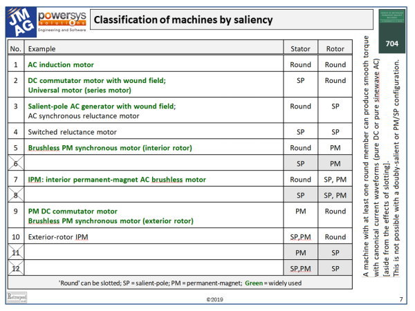
In the permanent-magnet machines 5–8, the magnet is on the rotor, while in 9–12 it is on the stator. Machines 5 and 9 have almost no saliency, because of the fact that the recoil permeability of the permanent magnets is very close to 1 (typically 1·05–1·1). So we see that saliency is a primarily a property of the permeability of the soft iron parts of the stator or rotor, as well as their shapes. To test for saliency, remove the magnets. Machines 6, 7, 8, 10, 11, and 12 are all salient-pole machines.
(4) Saliency can be useful. Probably the most common example of the usefulness of saliency is in the IPM (interior permanent-magnet motor), 7. Usually the torque in the IPM is considered to have two components, magnet alignment torque and reluctance torque. The reluctance torque is associated with the saliency, and particularly with the difference between \(L_d\) and \(L_q\), the synchronous inductances in the d– and q-axes respectively. Sometimes the ratio \(L_d / L_q\) is taken as a measure of the saliency.
How is this useful? At high speed the stator current or MMF vector can be rotated relative to the rotor in such a direction as to oppose the magnet flux, reducing the generated EMF and making more of the applied terminal voltage available to drive current in the q-axis, which is normally the torque-producing component. When this is done, the reluctance torque is also increased, and this is often claimed to be a major advantage of the IPM over the surface-magnet motor.
A theoretical point is worth making here. In the conventional analysis of the IPM the magnet alignment torque and the reluctance torque are almost always treated as separate entities, effectively relying on the principle of superposition. But because of the highly nonlinear magnetic circuit, this separation is not unique; and it is possible by a suitable reference-frame transformation (or a modification of Park’s transformation) to change it so that the torque appears to be a single entity, still dependent on the magnitude and orientation of the current vector, but with a different table of profiles. While this may seem to be rather academic, in fact it is important in practice, because finite-element calculations produce only a single unified figure for the torque, and there is no unique way to partition this figure into magnet-alignment and reluctance torque components.
Finally the table associates the 12 machines in the saliency chart with actual machines found in common practice. The empty rows 6, 8, 11, and 12 do not imply that machines in these categories are impossible, but they would have little practical use except possibly as rotary couplings. Such couplings can be used to transmit torque through the wall of a tank containing liquid foodstuffs or noxious liquids, thus avoiding seals. But of course both the stator and the rotor would have to rotate, and no energy conversion would take place.
A useful exercise is to write down the type of winding that would be used with each of the 12 categories of machine, together with the nature of the current waveform and whether a commutator is needed, or a power-electronic converter.

