 Fig. 1
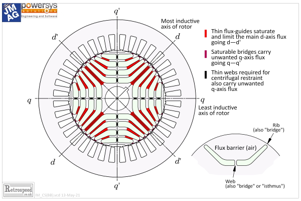
In Column 31 we deduced several inherent features of the switched reluctance motor merely by inspecting its cross-section and considering the main flux-paths, and here we will do the same for the synchronous reluctance motor, Fig. 1. The term synchronous refers to the fact that the rotor rotates in synchronism with the rotating magnetic field, at the so-called synchronous speed which is equal to the supply frequency divided by the number of pole-pairs. The synchronous reluctance motor is a pure AC motor and it requires a sinusoidal AC polyphase current, usually supplied by a dedicated 3-phase current-regulated PWM inverter. Synchronism is maintained by controlling the phase of the current, usually with the help of a shaft-position signal obtained from a resolver or equivalent transducer, although some systems have electronic shaft-position detection and are called sensorless. All these statements apply equally to the permanent-magnet brushless AC motor, whether of the surface-magnet or interior-magnet type, and also to the wound-field AC synchronous motor. So it is acceptable to regard the synchronous reluctance motor as a synchronous AC motor without magnets.
The induction motor is also an AC motor but it rotates at a speed slightly different from the synchronous speed; in other words it slips relative to the rotating magnetic field, and for this reason it is often called the asynchronous motor. In a certain sense, the switched reluctance could also be said to be “synchronous”, since its speed is fixed by the frequency of the current pulses fed to its stator windings. However, the relationship between speed and frequency is conditioned by the “vernier” nature of this doubly-salient motor, in that the apparent rotation of the field is not at the speed of the rotor (and in certain cases is even in the opposite direction). So although these features may be interesting from a theoretical point of view, it would be mischievous to refer to the switched reluctance motor as a synchronous motor, particularly as it is definitely not an AC motor and does not use a conventional AC inverter. The synchronous reluctance motor, however, is quintessentially a synchronous AC motor. To complete this brief overview, we might stop to consider the contrasting case of the DC commutator motor in which the speed is controlled purely by the voltage and the field current, the supply frequency being zero.
In all AC motors (and in the switched reluctance motor), while the speed is controlled by the frequency, the voltage must also be controlled in order to maintain the correct flux level. This is true even for permanent-magnet and wound-field motors, because only part of the flux is provided by the magnets (or the field current). In the synchronous reluctance motor (and the induction motor) all the flux is established by a component of stator current — the magnetizing current. In power-systems parlance both these motors always absorb reactive power, so in the motoring condition they operate with a lagging power-factor. This increases the apparent power or volt-amperes required from the inverter, and reduces the power-factor. The term power-factor is not used as much as it is with line-start motors, probably because the ratio of power and volt-amperes (the true power-factor) is spoiled by the voltage harmonics at the inverter output terminals; but the fundamental power-factor (considering only the fundamental time-harmonic components of voltage and current) is still important in understanding the operation of the motor.
The synchronous reluctance motor has, over the years, acquired a reputation for poor power-factor, with the implication that it needs a larger inverter than, say, an induction motor at the same power level. Let’s look into this, remembering that the power-factor of all variable-speed AC motors is not fixed but depends on the operating condition, which may vary over a wide range. There is a common belief that the synchronous reluctance motor should be designed to have the highest possible saliency ratio, that is, the ratio of the synchronous inductances in the two axes. Several mechanical and electromagnetic constraints limit the achievable saliency ratio. In Fig. 1 the axis of maximum synchronous inductance (in a frame of reference rotating at synchronous speed) has been designated the d-axis, while the q-axis is the low-inductance axis. This choice results in so-called “normal saliency” (Xd > Xq) in common with wound-field motors but in contrast with the interior permanent-magnet motor (IPM) which has inverse saliency (Xd < Xq). It is obvious why this occurs if we consider that q-axis flux (excited by the q-axis component of stator current) has to cross the flux-barriers, which constitute a path of high reluctance and therefore low inductance. On the other hand, d-axis flux passes along the flux-guides, which are intended to provide a path of lower reluctance and therefore higher inductance.
In Fig. 1 the flux-guides follow, more or less, the 4-pole pattern of flux lines that would be obtained without the rotor; (see Column 19 in this series). This is in fact one of the guiding principles in the design of the synchronous reluctance motor: it draws on the concept of an anistropic rotor in which the natural flux lines meet no resistance, while the cross-path flux-lines (which would coincide with the equipotentials in the natural magnetic field) meet an infinite resistance. Of course here we are using the term resistance to mean “magnetic resistance” or reluctance, and we are contemplating a distributed, anisotropic reluctance. The perfect anisotropic rotor is not physically realizable, but it serves as a benchmark that represents the maximum theoretically possible saliency ratio. The closest approach to it in practice is probably the axially-laminated rotor described by Anderson in about 1966, [1]; but this motor has not been pursued because of problems with assembly and also with excessive rotor core-loss. Most synchronous reluctance motors today use a unitary transverse lamination as in Fig. 1.
The rotor lamination is a tough proposition for the die-maker. In each quadrant it has four flux guides alternating with four flux-barriers, while along the d-axis a series of narrow webs holds the flux-guides together. The flux-guides are also linked by bridges at the extreme ends of the flux-guides near the rotor surface. On the inside their circular shape helps to stiffen the structure and reduce the risk of fatigue failure, as well as making the rotor a little less susceptible to impact damage during handling. The d-axis webs also have fillet radii where they meet the flux-guides, for similar reasons. Unfortunately both the webs and bridges constitute magnetic short-circuits which tend to reduce the saliency ratio, so they are made as narrow as can be permitted by mechanical considerations. Beyond that, saturation is the only way that the effect of these magnetic short-circuits can be limited.
One’s immediate impression of the rotor in Fig. 1 is that it has an awful lot of holes, and so it must be light in weight, with a low inertia that might help to improve the torque / inertia ratio. Indeed one Japanese manufacturer has used the synchronous reluctance motor as a servo motor, an application in which torque / inertia ratio is important. On the other hand, the rotor of Fig. 1 looks quite flimsy, and not well suited to withstand massive torque transients. As we’ve observed, handling could also be problematic on the factory floor or in the service shop, for while the rotor looks solid enough from the outside, it is actually quite fragile.
Many early works were preoccupied with maximizing the saliency ratio [2], but it is easy to forget that the rotor needs to be designed to carry adequate flux without undue saturation of the main flux path and without requiring excessive magnetizing current (which in Fig. 1 corresponds to the d-axis current since the d-axis is the main flux axis). Narrow flux-guides work against this, and Fig. 1 in particular looks like a rotor with limited flux-carrying capacity. If we compare it with a typical induction motor, this becomes even clearer. Even though the induction motor rotor has slots, they are seldom deep enough or narrow enough to limit the flux unduly.
To help in maximizing the flux (and minimizing the magnetizing current), the air-gap needs to be small — just as in the induction motor. This naturally tends to exacerbate the effects of permeance harmonics which produce torque ripple and additional losses on the rotor. In the early days there was a supposition that a large number of finely structured flux-guides was necessary, but it was shown by Professor Vagati and his colleagues in an elegant series of works in the 1990s that a satisfactory design can be made with only three or four flux-barriers per pole; [5]. Vagati codified several design rules including some which reduced both the torque ripple and the rotor core losses.
One of many interesting features demonstrated by Vagati was the extraordinary short-time overload capacity of the reluctance motor, which is not limited by the risk of demagnetization of permanent magnets; (nor is the magnetic behaviour particularly sensitive to temperature). Of course this requires an inverter with sufficient amperage.
On the other hand, while a temporary torque boost may be possible, the same is not true for the speed. It is obvious that the rotor in Fig. 1 is not suitable for high speeds. Quite apart from the issue of retention against centrifugal loading, the lateral stiffness is limited because of the small shaft diameter; and although the shaft diameter may be comparable to that of an induction motor, there is no cage of conductors to provide additional stiffening — there is just a spongy wad of laminations which retain appreciable lateral compliance even when clamped from the ends. Welds along the rotor surface are unthinkable for obvious reasons (electrical as well as mechanical). The mechanically-limited speed capability of the synchronous reluctance motor is a cruel irony to the electrical engineer, because it has been shown that the magnet-free reluctance motor has, in its ideal theoretical form, an infinite speed range, (though not at constant power), [4]. This is in contrast to certain classes of permanent-magnet motor which require ever-larger inverters to make them go fast; [4,6].
Given that the rotor of Fig. 1 is full of holes, it is natural to ask whether it could not be improved by fitting magnets in the holes? We would then have a permanent-magnet-assisted synchronous reluctance motor, and if we added enough magnets we could call it a hybrid PM/reluctance motor. This enters into the continuum of motors with both reluctance torque and magnet-alignment torque, and of course we see today the fantastic variety of embodiments not only in patents and academic papers but also in production. We are perhaps more conscious of hybrid motors that use high-energy magnets, but there is a class of PM-assisted reluctance motors that use ferrite magnets, and in principle these might offer some relief from the high risk of reliance on rare earths. (See [3]).
The magnet-free — or even the “magnet-lite” — AC brushless variable-speed inverter-fed motor is a dream held by many engineers, notwithstanding the often-overlooked fact that the induction motor could be said to be the archetype of this class of motor, already available. The prospects for the synchronous reluctance motor might be improved if only we tempered our hunger for performance in our automotive vehicles, and settled for calmer, slower ways of going about our business.
References
- [1] Cruickshank A.J.O., Anderson A.F. and Menzies R.W., Theory and performance of reluctance motors with axially laminated anisotropic rotors, Proceedings IEE, Vol. 118, No. 7, pp. 887-894, July 1971
- [2] Staton D.A., Miller T.J.E. and Wood S.E., Maximising the saliency ratio of the synchronous reluctance motor, IEE Proceedings-B, Vol. 140, No.4, pp. 249-259, July 1993.
- [3] Soong W.L., Staton D.A. and Miller T.J.E. , Design of a new axially-laminated interior permanent-magnet motor, IEEE Transactions on Industry Applications, Vol. 31, No. 2, pp. 358-367, March/April 1995.
- [4] Hendershot J.R. and Miller T.J.E., Design of Brushless Permanent-Magnet Machines, published by Motor Design Books LLC, ISBN 978-0-9840687-0-8, (822pp)., 2010. Available from sales@motordesignbooks.com.
- [5] For papers by Professor Vagati, search IEE Xplore “Vagati + Synchronous Reluctance”.
- [6] Soong, W.L. and Miller T.J.E., Field-weakening performance of brushless synchronous AC motor drives, IEE Proceedings, Electr. Power Appl., Vol. 141, No. 6, pp. 331-340, November 1994.
- [7] Credo A., Fabri G. and Villani M., The design of high speed synchronous reluctance motor by a topology optimization, Electric Motor Engineering, December 2020, pp. 20-24
Use this form to send us your comments. Your valuable feedback will be used for future reference.
Please note that we will not answer any questions. Thank you in advance for your understanding.
Caution: This entry form is for English only. Please refrain from using multibyte characters such as Japanese, Chinese, and Korean.


