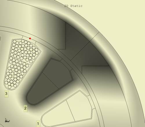
 Fig. 1 Intensity map of vector potential
In the armature of a permanent-magnet DC motor, the wires usually occupy a rather untidy pattern in the slot — not because there is anything wrong, but simply as a result of the winding process. A similar pattern is found in induction motors with random windings (sometimes called mush windings). A typical cross-section is shown in Fig. 1, in which the individual wires are depicted in just one of the slots, slot 3.
We can see in slot 1 that the winding space is partitioned into two sections of equal area, reflecting the fact that this type of winding is often divided into layers. In some cases there may be more than two layers, but here we need consider only two. The two layers might belong to different parallel paths in the winding, and when that is the case we immediately run into the familiar question as to whether the slot-leakage inductance is the same for both paths. It is not. Less often considered is whether the generated EMF is affected by the positions of the wires in the slot. If the EMFs in two parallel paths are different, the currents will differ, even with DC ; and this is equivalent to having a circulating current between the paths, which is not observable at the terminals and is liable to cause heating and loss of efficiency. The question is at least as important as the question about the slot-leakage inductance.
Fig. 1 is an intensity plot of vector potential calculated in JMAG under open-circuit conditions in a permanent-magnet DC commutator motor with ferrite magnets. This calculation was set up to study the possibility of variation in the EMFs of different coils, depending on the positions of their wires in the slot. Let us say we have a “go” wire j in slot 3, for example, continued as a “return” wire k in slot 7 (not shown in Fig. 1). The flux-linkage of that single turn is approximately (Aj3 − Ak7) [Wb/m] multiplied by the active length of the armature, where Aj3 means the vector potential at the location of wire j in slot 3, and so on. The result is approximate because it does not include the effect of “magnet overhang” or “shell overhang”, in which the axial lengths of the armature, the magnets, and the shell are all different. Moreover it does not take into account the end-windings. But the 2D formula is a good starting-point from which to seek guidance on the question of EMF differentials between turns according to the positions of their wires in the slot.
In the position shown in Fig. 1, the vector potential is strong or high in the interpolar region, and low elsewhere : dark = strong, light = weak. Indeed it appears to be strongest in the air regions (including the interior of the slot), although it is not quite zero in the magnets or the steel parts. This is fortunate because we want to locate the wires such that the flux-linkages of the turns are as high as possible, in order to get the greatest possible EMF from a given quantity of magnet, copper, and iron.
The shading in Fig. 1 shows no perceptible variation in vector potential throughout the slot, even extending into the air-gap outside the slot. More precise values obtained with a numerical probe suggest that the variation is less than 0⋅1% across the entire slot.
At first sight this extraordinary result seems to suggest that the positions of the wires in the slot do not affect the EMF generated in different turns, and therefore in different sections or parallel paths of the winding. However, it is risky to draw conclusions from a 2D analysis in cases where 3D effects may be significant, and this is certainly the case with DC permanent-magnet motors (especially those that use ferrite magnets) because of the common practice of making the axial length of the magnets greater than that of the armature, and the axial length of the shell greater than that of the magnets. What we can say is that if there is a difference in path-EMFs, it is likely to be attributable to the disposition of the end-windings and the conformation of the magnetic field outside the active length, and not to the positions of the wires in the slots per se.
For induction motors and other types of permanent-magnet motor (including brushless motors) where these “overhangs” are not used, the end-effects are normally negligible and we can take it that the positions of the wires in the slots are not important to the rotational EMF. Even so, this conclusion should be tested using a simple finite-element calculation such as the one in Fig. 1, if the conditions are markedly different from those of Fig. 1. For example, at higher levels of flux-density in the steel, we would expect more variation of vector potential in the slots. We might even want to check the effects of wider slot-openings, or of eccentricity, or of flats, holes, notches, key-ways and other irregularities, although these would be expected to be small in most cases.
These reflections prompt an interesting observation about the theoretical basis of the calculation of EMF, and here it is probably sensible to restrict our attention to rotational EMF : that is, the EMF that is attributable to rotation alone. It is tacitly assumed that everyone knows that the EMF in a turn is the rate of change of its flux-linkage, so if we calculate (AGO − ARETURN) as a function of rotor position, we have only to differentiate this expression with respect to time, and multiply it by the armature length, to get the EMF. The simplicity of this process (especially when implemented in the context of finite-element analysis) is remarkable, and it is especially appealing because it is a direct implementation of Faraday’s law. It is remarkable that few classical text-books on electrical machines approach the EMF calculation on this basis. It is more common to come across the “flux-cutting” formula in which the air-gap flux-density is multiplied by the armature length and the peripheral velocity, with reference to the Lorentz formula v × B for the EMF in an isolated conductor (which cannot be measured), and a caveat that it applies only to unslotted structures where the conductors lie on the surfaces of smooth cylinders (as they once did, 140 years ago).
Many serious authoritative works on the design of AC and DC machines use this formulation, even though some of them recognize that when the wires are in slots they are in a region of almost zero flux-density. The paradox can be resolved with a modicum of rigour by means of arguments which effectively say that as the rotor rotates the wires cut the flux-lines even while they are buried in the slots and never actually experience contact with them. Indeed the notion of “cutting” flux-lines is really quite absurd, and would surely raise Gauss from his grave; “passing through” might be a better term, rather like a bamboo pole passing transversely through a rain shower. The result is a working formula for EMF, although it relies on the concept of a static flux distribution which fails to take permeance harmonics into account. This static flux-distribution should really be taken at the surface of the armature, but it is often taken in the middle of the air-gap because the field becomes so distorted near the slot-openings. The space-harmonic content is often dismissed in AC machine theory while retaining only the fundamental, while in DC machine theory the total flux is accumulated. In both cases the hideous distortion of the flux by the slots is altogether bypassed.
Although surface-mounted conductors were widely used for many years before 1890 (not only in the Gramme ring armature but also in early drum armatures), the practice of laying conductors in slots was widely developed in the 1890s for both AC and DC machines. (Indeed it can be traced back to Pacinotti in 1860). The calculation of the magnetic field of cylindrical slotted components was far beyond the available methods of the time, and it is only since about 1970 that modern numerical analysis has overcome this limitation. For more than a century after 1902, the industry made heavy use of Carter’s coefficient, originally derived by conformal mapping for a singly-slotted air-gap in rectangular coordinates, using the Schwarz-Christoffel and related transformations. What Carter’s coefficient does is to replace all the conductors in a slot by a single filament located at the slot centre-line on the armature surface, as depicted by the red dot at the opening of slot 3 in Fig. 1. In design calculations the magnetic field is calculated assuming a smooth surface with no slotting, but with a dilated air-gap whose length is given by Carter’s analysis (usually replaced by close-fitting but simpler formulas that take parameters from the geometry near the slot-opening). When in the glowing hindsight of a modern finite-element analysis we shrink Carter to that red dot, we can begin to appreciate the tremendous adventurousness of his analysis more than 120 years ago. At the time it must have seemed to some engineers that he was reducing the slotted armature to its surface-wire predecessor — a fully justifiable interpretation; and we could perhaps be forgiven for thinking that he might have been “dumbing down” what must have seemed a formidable theoretical difficulty. No wonder he became and remained famous for more than a century.
From one point of view this method seems to be an all-powerful yet simple practical way to deal with the otherwise impossible problem of the slotted geometry, and there is no doubt about its effectiveness and its pedigree and its popularity. However, it neglects the permeance harmonics (that is, modulation of the flux by the passing slots), so it cannot predict the pernicious EMF ripple that has plagued many a machine designer over the years; and what could be said to be worse is that it facilitates and even encourages the use of the v × B formulation of the EMF in a single conductor, which is utterly wrong for a real electric machine in this day and age.
We should not dismiss the traditional design methods lightly, however, because they have given us almost all the motors ever manufactured on this planet. But today we should be wary and perhaps gently critical of text-books that fail to address this vital topic seriously; and we should perhaps celebrate the extraordinary fact that the finite-element method — the most modern and advanced tool for electromagnetic analysis — is so well adapted to the calculation of vector potential (and hence flux-linkage and EMF) according to the direct application of Faraday’s law. It does so without the need for contemplating the unmeasurable EMF generated in isolated conductors, or for assuming that conductors lie on the surfaces of smooth cylinders, or for dilating the air-gap length to some unverifiable equivalent value.
Just imagine if the Victorian engineers in 1880 had seen Fig. 1, and if they had had someone like Oliver Heaviside — or a modern finite-element program — to take the terrifying sting out of the abstruse notion of vector potential. In modern parlance they might shout out, “Guys, we can use slots! Yippee!” although at the time the announcement might have been more florid: “Ladies and Gentlemen, be assured that the placement of conductors in slots will have no adverse electromagnetic effect on the performance of our dynamo-electric machines”. *1
Finally we should not infer from Fig. 1 that the inductance is independent of the positions of the wires in the slots. It is well known that inductance is strongly dependent on the positions of the wires in the slots, and we see this most often in the calculation of the slot-leakage components of self- and mutual inductances of windings, in all types of motor. Fig. 1 simply does not apply in this case, because the excitation is the current in the slot itself, not the magnets outside the slot. The slot-leakage field looks completely different. Try it!
Further reading
- Carter F.W., A Note on Airgap and Interpolar Induction, J.I.E.E., Vol. 29, p. 925, 1900.
- Bianchi N., Electrical Machine Analysis Using Finite Elements, Taylor & Francis, 2005.
- Lowther D. and Silvester P.P., Computer-Aided Design in Magnetics, Springer, 1986.
- Bewley L.V., Flux Linkages and Electromagnetic Induction, Macmillan, 1952.
- Walmsley R.M., Electricity in the Service of Man, Cassell, 1904.

