 Fig. 1
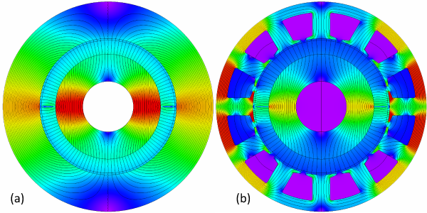
The number of poles is perhaps the most basic parameter in the design of an electric machine. When we speak of this parameter, we usually mean the number of working poles. Fig. 1 shows, for example, a machine with 2 poles which we count as the number of magnets. More precisely, we might count the succession of N and S (north and south) polarities at the rotor surface. In Fig. 1 the result is 2, and we often write this as p = 1 pole pair. Fig. 1(a) is just about the most primitive configuration possible, with a radially-magnetized magnet and no slots or stator winding. But still we can learn several important principles from it.
In AC machines the air-gap flux distribution is tacitly assumed to be sinusoidal, and the number of pole-pairs is the number of complete cycles p in the flux-density distribution around 360\(^{ \circ }\). More precisely, we understand p to mean the number of complete cycles in the fundamental space-harmonic component of the flux-density distribution.
This distinction is important because the actual distribution of flux crossing the air-gap is generally not a pure sine-wave. This is true for both components of the flux — the magnet flux and the armature-reaction flux produced by the stator current. We therefore focus our attention on the fundamental space-harmonic components of both of them; and we understand that these components rotate in synchronism at the synchronous speed, and combine to produce the average or running torque. These components identify the so-called working harmonic.
The analysis of the “machine” in Fig. 1(a) often begins with a Fourier series analysis of the flux-distribution around the air-gap, Fig. 2. (Not the FFT!) The red graph is a simple rectangular approximation calculated by analytical formula, assuming that the steel is infinitely permeable in the stator and rotor cores. (See, for example, the Green Book [2010,2022]).
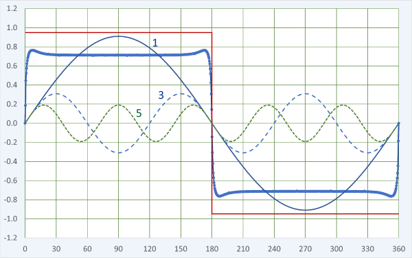 Fig. 2
The finite-element result is the thick blue graph, and we see a significantly lower flux-density level because of the saturation of the cores. The saturation is clear in Fig. 1(a), especially around the 3 o’clock and 9 o’clock angles.
The fundamental space-harmonic component is labelled 1, and it has a value of about 0.91 T. (The magnet remanent flux-density is 1.2 T and its relative recoil permeability is 1.05). In a 2-pole AC machine with a 2-pole winding, we would focus on this component to calculate the fundamental time-harmonic of the phase EMF, and we would expect this component to interact with the fundamental space-harmonic of the winding MMF to produce the mean running torque.
The actual flux-distribution is obviously not a pure sinewave. It has prominent harmonic components. The 3rd and the 5th are shown in Fig. 1, but there are many more. When the field is symmetrical and the rotor is centred, there are no even-order harmonics. Since the flux distribution is nearly rectangular, the amplitudes of the harmonics are approximately inversely proportional to their harmonic orders; here the 3rd is roughly 0.31 and the 5th, 0.19. The harmonics of the magnet flux distribution rotate at the same speed as the rotor, and they generate EMF in the stator winding. Even though we have not yet drawn a stator winding, we can say that the nth flux harmonic will generate a harmonic EMF at n times the fundamental frequency, and it will distort the terminal EMF.
If we want a machine with a sinusoidal terminal EMF, we generally adopt two parallel approaches. One is to minimize the space-harmonics in the magnet flux distribution. This requires some kind of profiling of the magnetization, and the ultimate method is the Halbach array (see the Blue Book [2022]). Simple arrays of parallel- or radially-magnetized surface magnets can be dimensioned to reduce selected harmonics, but not to eliminate all the harmonics simultaneously. In the interior-PM motor (the IPM), quite complex rotor geometries are sometimes devised to help reduce the harmonics, especially the lower-order ones.
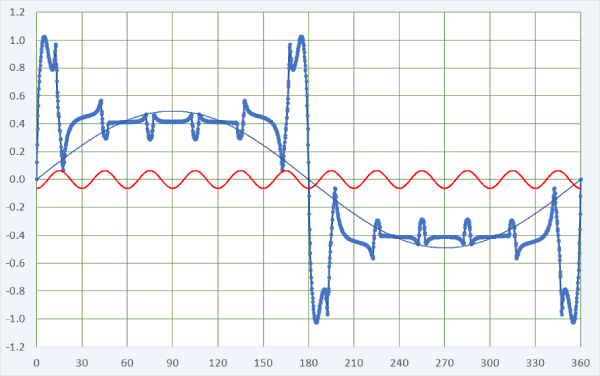 Fig. 3
The second approach is to arrange the stator winding to attenuate the linkage of particular harmonic flux components. This is normally achieved through the pitch and distribution factors; by using a non-integer number of slots/pole; by skew or step-skew; and by star connection of the phases.
When the stator is slotted, many more harmonics appear in the magnet flux distribution, and we can see this by adding slots as in Fig. 1(b). This is a very bad machine, but with JMAG it is easy to see precisely what is wrong with it.
First, we can see much greater variability of the flux-density in the flux-plot. The slots have seriously disrupted the nice smooth flux pattern we saw in Fig. 1(a). Their effect is reflected in the air-gap flux distribution in Fig. 3. As engineers we might immediately notice that the precious fundamental space-harmonic component has decreased to 0.49 T — roughly half of what it was before we introduced the slots. This goes with the huge reduction in the actual flux-density from about 15\(^{ \circ }\) to 165\(^{ \circ }\), a big ‘crater’ where previously we had nearly 0.9 T all the way across this region. The reduction is due to the extreme saturation of the stator core near the 3 o’clock and 9 o’clock positions. This saturation constricts almost the entire flux. In passing, we can say that the region of intense saturation is around the so-called quadrature axis; since the quadrature axis rotates with the rotor, so does the saturated region.
Fig. 3 also shows (in red) the 12th harmonic of the flux distribution, amplified by a factor of 10 to make it easier to see the correlation of this harmonic with the notches caused by the slot-openings. The slot-openings are obviously stationary, so the notches do not rotate with the rotor. The 12th harmonic therefore does not rotate with the fundamental harmonic. We normally consider the effect of the slot-openings as a modulation of the flux distribution at the slot-passing frequency, and it gives rise to a ripple in the generated EMF at this frequency. Unfortunately it cannot be attenuated by the coil pitch or the the winding distribution, and although it is greatly reduced by means of a non-integer number of slots per pole (fractional slots/pole), it is sometimes necessary to skew or step-skew the rotor to get rid of it. (This reduces the cogging torque at the same time).
We have only scratched the surface in observing the pattern of harmonics, and we haven’t even added a stator winding!
But without considering the winding at all, let me pose a question. By changing one single parameter in the configuration of Fig. 1(b), can you obtain a much more practical design?
Answer in the next Diary, No. 47.
References (available shortly) :
- Green Book : J.R. Hendershot and T.J.E. Miller, Design of Brushless Permanent-Magnet Machines, ISBN , 2010 (Hardback); 2022 (on-line, with corrections)
- Blue Book : J.R. Hendershot and T.J.E. Miller, Design Studies in Electric Machines, Motor Design Books LLC, ISBN , 2022 (Hardback and on-line)

