 Fig. 1
In Engineer’s Diary No. 46 we discussed the harmonic poles of a 2-pole rotary machine. ‘Harmonic poles’ refers to the space-harmonics of the flux distribution around the air-gap. We calculated this distribution using JMAG, and then we made a Fourier series analysis to obtain and display its space- harmonic components.
The example in Diary No. 46 was described as a very bad electric machine, and we posed the question, how would you obtain a more practical design by changing just one parameter? Before we go further, we should answer that question by suggesting that the number of poles should be increased from 2 to 10. Readers may be interested to try these models for themselves, but the resulting 12-slot 10-pole machine is a good example and it is described in great detail in the forthcoming Blue Book, chapter 4.
It was pointed out in Diary No. 46 that all the harmonic poles produced by the magnet rotate with the rotor at synchronous speed, and induce time-harmonic components in the EMF at harmonic frequencies corresponding to the space-harmonics of the flux distribution.
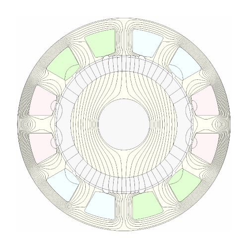
Here we turn our attention to the flux distribution produced by the ampere-conductors of the stator winding, and Fig. 1 shows a flux-plot obtained with the winding connection shown in the small inset diagram in Fig. 2. This is a static flux-plot taken at one instant when the current in phase U is at a positive maximum giving a current-density of 6 A/mm2 in the red slots. With balanced 3-phase currents the current-density in the green and blue slots is −3 A/mm2 at that instant.
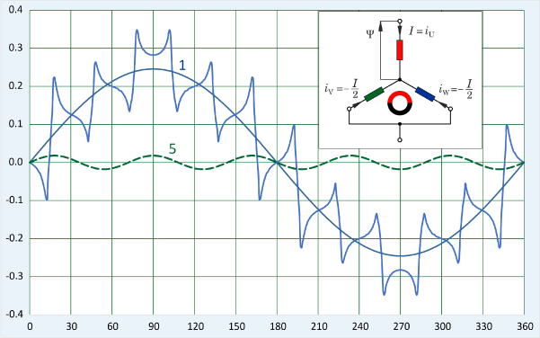 Fig. 2
Now we need to think about the behaviour of the space-harmonics produced by the stator current. These harmonics are important because they contribute to the differential leakage inductance and they also cause eddy-current losses on the rotor. The process of analysing them to find their magnitudes is exactly the same as for the space-harmonics of the magnet flux-distribution, and we can see this in Fig. 2. (This corresponds to Fig. 3 in Diary No. 46). The flux-density graph in Fig. 2 is taken at the magnet surface, and we can see the pronounced effects of the slot-openings. The graph is also a function of the radius at which it is measured; but both of these effects will be ignored here, in order to concentrate on the behaviour of the space-harmonics and particularly their speeds and directions of rotation.
To begin, let us consider the flux distribution as a whole. At the instant shown, the current in the three phases can be characterized by the notation U/vw. Capital U means positive peak current in phase U; while after the stroke symbol lower-case v and w mean that the currents in phases V and W are −½ the positive peak. With balanced currents, the condition V/wu will occur 120° later in the electrical cycle. After a further 120°, we will get W/uv. This sequence repeats indefinitely. It must be the case that at each of these instants, the magnetic field looks exactly the same as it does in Fig. 1, but rotated through 120°.
This is a simple way to explain the rotating magnetic field produced by a stationary set of windings displaced from one another by 120° around the stator, and fed with balanced 3-phase currents. If the states U/vw, V/wu, W/uv were switched instantly at 120° intervals, the field would also switch or jump in position by 120°, and this is more or less what happens in a brushless DC motor which operates with so-called ‘block commutation’ and pulses of constant DC current 120° wide in each phase. But when the current waveforms are sinusoidal, and the winding is ‘sine-distributed’, the field rotates smoothly — more or less.
We know that it is impossible to make a perfectly sine-distributed winding. The 2-pole winding in Fig. 1 has two full-pitch coils per phase. Effectively it is a lap winding with 2 slots per pole per phase and a phase spread of 2/12 × 360 = 60° — quite a conventional arrangement which can be found in machines of any pole-number. This example is simple but also practical, and we can proceed to consider its space-harmonics.
Before we go further, it might be interesting to take a ‘philosophical’ view of the process, because we are in fact at the junction of the two tectonic plates of numerical field analysis (Fig. 1) and classical machine theory (Figs. 2 and 3). In particular we can see how well these two approaches work together.
Fig. 2 shows the actual flux distribution, as we have noted, and two space-harmonics: the fundamental (1) and the 5th (5), both obtained by Fourier series analysis of the actual distribution (not the FFT!).
While the “stepping” argument above tells us about the general rotation of the field as a whole, it tells us nothing about the rotation of the harmonics. We might have a strong inclination to believe that the fundamental rotates at the synchronous speed, 120 electrical degrees in space in 120° of the time waveform — and we’d be right. But the rotation of a harmonic such as the 5th is by no means easy to visualize. We certainly cannot see it in Fig. 1 — indeed we cannot see any harmonics in Fig. 1 — and we cannot see any rotation in Fig. 2 either. It is at this point that the classical theory turns to a mathematical argument.
Although it is abstract (i.e., hard to visualize), the mathematical argument is actually rather a simple one since it employs nothing more than basic ‘school’ trigonometry. Yet the following quotation underlines its enormous importance in electrical engineering (and machines in particular):
— J.A. Bridge
Let’s see how it works.
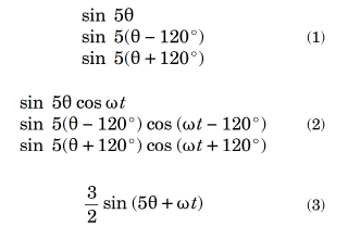 Fig. 3
The key expressions are summarized in Fig. 3. Although the argument is expressed for the 5th harmonic, it can easily be repeated for any harmonic. In (1) we see three sinewaves representing the distribution of MMF around the stator periphery. The same expressions could be used for ampere-conductors per metre or per radian, or for flux-density. The angle θ is here expressed in mechanical degrees (actual degrees, not electrical degrees), but if we are considering a 2-pole motor as in Fig. 1, there is no difference. All three expressions have the same form, but the second and third expressions are phase-shifted by 120°, reflecting the fact that the axis of phase V is displaced 120° in the forward direction from the axis of phase U, and the axis of phase W is displaced 240° (equivalent to −120°) from the axis of phase U. To put this another way, the origin of the first sine function is at θ = 0; that of the second is at +120°, and that of the third is at −120°.
In (2) the amplitudes of the harmonic waves of MMF are modulated by the currents flowing in the three phases, which are represented by the cosine functions. Note that the currents are balanced: they all have the same amplitude (1) and they are phase-shifted in time by 120°. The phase sequence is UVW.
The analytical result (3) is obtained by standard manipulation of the trigonometric products into sum-and-difference terms, and then adding all terms together. It represents a field that is rotating backwards at the speed ω/5, and whose amplitude is 3/2 times the amplitude of the field of any individual phase. To see how the speed is deduced, consider the peak of the expression in (3). It corresponds to the argument 5θ + ωt = 0. Therefore θ = −ωt/5. As time progresses, the position θ corresponding to the peak of the wave must go backwards at the speed ω/5. This is 1/5 of the speed at which the fundamental harmonic travels, or 1/5 of the synchronous speed.
This is a striking result. It means that in general, the space-harmonics of the stator MMF rotate at their own speeds — sub-multiples of the synchronous speed — some of them in the backward direction and some in the forward direction. They are asynchronous. That means they are moving relative to the rotor, and they tend to generate eddy-current losses in any conducting components on the rotor (including the magnets). For example suppose the rotor is rotating at 1200 rpm. The 5th harmonic is rotating at −240 rpm. Relative to the rotor it is rotating at 1440 rpm, or 6/5 per-unit speed. But it has 5 pole-pairs, and therefore it generates eddy-currents at a frequency of 5 × 6/5 = 6 times the fundamental frequency.
The calculation of these eddy-currents is by no means simple. While analytical treatments can be used in simple cases (discussed in the Green Book), accurate calculations often require direct numerical simulation, in which the resolution into harmonics generally does not appear. However, the classical harmonic analysis remains a powerful tool to help us understand where the problems are coming from, and how we might design the winding to reduce the effects. It is also important in the calculation of winding factors and differential leakage inductance, both of which are needed elsewhere in the design calculations. So again we can see the remarkable ways in which the classical theory interacts with numerical analysis. We are fortunate to have both.
References
- Green Book : J.R. Hendershot and T.J.E. Miller, Design of Brushless Permanent-Magnet Machines, ISBN , 2010 (Hardback); 2022 (on-line, with corrections)
- Blue Book : J.R. Hendershot and T.J.E. Miller, Design Studies in Electric Machines, Motor Design Books LLC, ISBN , 2022 (Hardback and on-line)

