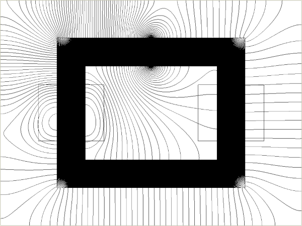
 Fig. 1 Flux linkage, leakage, fringing, and inductance
Readers may have noticed that Engineer’s Diary has been trying to follow the alphabet in selecting monthly topics, and some letters provide more ideas than others. This month, ‘L’ is rather special because it is the common symbol for inductance, a subject so near to the heart of every JMAG user. As to why ‘L’ should be the symbol for inductance, it was chosen in honour of Lenz who gave his name to Lenz’s law, which declares that electromagnetic induction (Faraday’s law) tends to drive current in such a direction as to annul the change in flux-linkage that caused it.
L is a circuit parameter measurable at the terminals of a circuit. It is not really a field quantity in the sense of distributed quantities like flux-density or magnetic vector potential. It is interesting that Maxwell himself produced formulas for the inductance of a number of circuits, even though we associate Maxwell with field analysis and the equations of electromagnetism. (See Engineer’s Diary No. 26 — The Remarkable Work of Rosa and Grover). It seems from the biographies of Maxwell, Kelvin, and Heaviside particularly that this work was very much at the forefront of developments in electric telegraphy, which was so vigorously pursued in the mid-to-late 19th century and really established the coming age of electricity.
At that time there were no electric machines to speak of — not even transformers. It was not until the 1880s and 1890s that serious development of power systems and machines began in earnest, and it is likely that the engineers engaged in this amazing evolution did not begin their work with the philosophical contemplation of inductance or even Faraday’s law. But very soon they had to reckon with all the fundamental laws of electromagnetism, and inductance reared its ugly head everywhere — in brush sparking, in the regulation of alternators, in the series voltage-drop in transformers, in the arcs formed when switches opened (or when circuits were interrupted by faults), and in the transmission of power through cables and overhead lines.
From the earliest days of the electric power industry, inductance had some nasty characteristics that were rare in the refined art of telegraphy. One of these was the effect of magnetic saturation (and even hysteresis). A second was the effect of rotation, which produced enormous variation in both self- and mutual inductances in electric machines. And a third was the painstaking realisation that the inductance of machines and transformers seemed to depend on aspects of the internal magnetic field that were impossible to calculate at the time. Indeed they were impossible to measure, and many of these aspects of the internal magnetic field still are impossible to measure.
By solving Maxwell’s field equations together with the nonlinear ‘constitutive’ properties of ferromagnetic materials, the modern finite-element method makes it possible to calculate almost all the details of the electromagnetic field including terminal quantities such as inductance, flux-linkage, and induced voltage. As we know, the capabilities extend far beyond these basic parameters to include force and torque, and even stress and temperature distribution, and the dynamics of cooling fluids.
But while the finite-element method is an ‘all-powerful’ tool for such analysis, it is important not to treat it as a ‘black box’. There is in fact no reason to treat it as a black box, because the facilities are available for investigating and illustrating even the simplest details and concepts, and for checking the calculations against rough ‘manual’ calculations (‘sanity checks’). Such elements as the mesh generator and the solver are, of course, presented to the user as a ‘black box’, and this is appropriate because they are so sophisticated and so complex that most users would not wish to be troubled with too much detail about how they work. What is much more important to the engineering user is the ability to see in detail the results of what they do (with such extraordinary precision and reliability), and to be able to interpret the results and make sure they make sense.
This is the approach taken in a series of four Videos, Nos. 36-39, in the JMAG video series. In these videos we analyse the field of a simple 2-winding transformer with a gapped core, and Fig. 1 shows an example of the leakage field calculated in JMAG. The objective of this 4-part series of videos is to clarify all the terms flux, flux-linkage, flux-leakage, and fringing; and to show how they are related to self- and mutual inductance and various forms of the equivalent circuit.
Video 37 (Part 2) begins the process of numerical calculation of key parameters of the magnetic field, especially the flux-densities in the air-gap, and at different points in the steel core.
Video 38 (Part 3) progresses to the calculation of the flux-linkage of the two windings, leading to their self- and mutual inductances and the coupling coefficient between them. It is shown how saturation affects all these values, and how the inductances can be incorporated in a simple T-equivalent circuit. The concept of short-circuit inductance is also introduced.
Video 39 (Part 4) takes the equivalent circuit further, developing alternative forms such as the Γ and L equivalent circuits used with field-oriented control theory, and relating them rigorously to the T circuit. These circuits are established for the general case where the primary and secondary windings have different numbers of turns and different physical configurations, and again the short-circuit inductance is illustrated in all cases. The video also discusses the standard IEEE and IEC tests for induction motors (the no-load test and the short-circuit test) and for transformers (the open-circuit test and the short-circuit test), and deals with the distribution of leakage inductance between the primary and secondary windings. This is relevant to the structure of the common Steinmetz equivalent circuit of the induction motor for positive-sequence quantities, and its equivalent in transformer theory.
All of the numerical data required for the development of the equivalent circuit is obtained from a set of straightforward computations using JMAG, and the theme of these four videos is to show how this data can be translated into the forms that appear in classical analysis and measurements of certain important types of electric machine.


