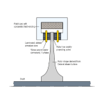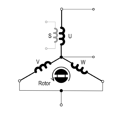
Fig. 1 Shadow-winding S used in a permanent-magnet brushless motor
The shadow-winding is useful for measuring generated EMF and inductance in prototype electric machines. Typically it consists of a complete phase winding wound in the same slots as one of the main phase windings, but with fewer turns and much thinner wire. 1
In many cases the slots are so tightly packed that any shadow-winding must be installed at the same time as the main winding, closely affixed to it by tapes to prevent mechanical damage. In some cases the packing is so tight that it is not feasible to insert a shadow winding at all. In a prototype it may still be possible to divide the main winding with tappings and an isolated section consisting of a small fraction of the turns in each coil, but if even this is not possible the shadow-winding will probably have to be abandoned.
Sometimes there is enough free space to permit the shadow-coils to be threaded through the slots after the main windings have been installed. This is practical especially with single-tooth windings with only a small number of coils per phase and a modest slot-fill factor. For example in a stator with only 4 coils per phase it is no great labour to wind four coils of 2 turns each in this way, making a total of 8 turns in series. If the entire winding has, say, 80 turns in series per phase, the induced voltage in the shadow winding will be only 10% of the induced voltage in the main winding. This applies to all induced voltages, whether they are caused by rotation (as in the EMF generated on open-circuit by a rotating permanent-magnet rotor); or by induction as a result of varying current in the main phase (self-induction) or in another phase (mutual induction).
The reduced voltage level has several advantages. It helps make for safety in the test area. Only low voltages need to be measured, which reduces or eliminates the need for voltage-dividers and permits the use of low-voltage laboratory test instruments. But by far the greatest advantage is that the shadow circuit does not carry any current. Its terminal voltage therefore does not have a resistive-drop component, but is purely inductive. This eliminates one of the main sources of error in inductance measurements. It also means that the heavy current leads can be kept away from the test bench (although the current transducers or ammeters must still be accommodated somewhere in the main phase circuits to provide current measurements).
Thin electrical leads and low voltage should not be permitted to lead to a false sense of total safety, however. If the shadow-winding circuit were to suffer a short-circuit while the machine is running, a very large fault current will be induced and it will almost certainly fail (‘blow’ in common parlance). 2 With permanent-magnet machines this risk is severe because the main source of excitation cannot be removed; and although it can be removed in wound-field synchronous machines or induction machines it may not be possible to extinguish the field before the fragile shadow-winding fails. To protect the shadow-winding against faults occurring outside the machine, it is recommended to consider electrical and mechanical means of protection for the entire shadow-winding circuit including those parts of it that lie outside the machine. These measures might include a fast-acting fuse together with sound wiring throughout, together with a safety screen or a complete enclosure.
The voltage induced in the shadow-winding will be a very close replica of the induced voltage in the main phase winding, provided that the magnetic coupling is tight. It should be possible to achieve a coupling coefficient of 0.98, and this should be adequate for most purposes in measuring both EMF and inductance. The close replication of the induced voltage in the main phase applies to all induced voltage, including the complete EMF waveform when running the machine at speed on open-circuit and the inductive component of the terminal voltage when running the machine on load. It is also convenient for making measurements with an electronic flux-meter or integrating voltmeter, using limited angles of rotation to measure flux-linkage changes directly.
Limited-angle rotation tests with a flux-meter are particularly useful in connection with permanent-magnet machines, for testing the open-circuit flux-linkage as a measure of the condition of the magnets. It is normal practice to check the magnets for partial demagnetization after testing the machine at full load or overload, and this can be done quickly and conveniently with the shadow-winding. Because the test is done with the machine essentially stationary, the magnet temperature can be measured precisely at the same time. Although the same test can be done with the main winding, the shadow-winding has the advantage of working at a lower voltage level. With star-connected windings it gives the phase voltage rather than the line-to-line voltage, and this is important because the phase voltage may not be readily accessible if the star point of the winding is “buried” in the end-windings. Moreover, when a shadow-winding is installed, it is often convenient to bring out tappings for a single-tooth coil at the same time. It may also be convenient to instal search coils to measure the flux-density in the stator yoke; and in integral-slot machines, full-pitch search coils may also be useful. All the shadow-winding and search-coil voltages and flux-linkages are useful in the process of design verification and trouble-shooting at the early stages of proofing, and there may be some engineers who on certain occasions wished they had thought of installing such coils before it was too late. They may be equally useful in monitoring the condition of the machine during load tests. For example, it may be convenient to connect a spectrum analyzer to the shadow-winding rather than the main winding.
For inductance measurement the shadow-winding really comes into its own. It is surprising that it is rarely mentioned in the literature, even though there are many good papers on inductance measurement in modern machines; (see, for example, [2]). The method is described in the Green Book [3] (with references to much earlier work on DC inductance measurement such as [4] and [5]); but it is given as a method for measuring mutual inductance. With a perfectly-coupled shadow-winding the measurement of mutual inductance becomes indistinguishable from the measurement of self-inductance. Even if the coupling coefficient is no higher than, say, 95‐98%, the simplicity of the method and its freedom from the complications involved with most other methods make it an attractive option. These advantages were recognized by Jones [4] and also in [5], and it is interesting that those early works were able to express the theory in only one or two equations, since nothing more was (or is) necessary. 3
With reference to Fig. 1, the method is to switch or reverse a current I in the range of normal value in one phase winding or in some special connection of the phase windings representing one instant in normal AC operation, and to record the change Δψ in flux-linkage in the shadow-winding. The change in flux-linkage of the main winding circuit is ΔΨ = (N/n) Δψ where N/n is the turns ratio between the main winding connection and the shadow winding; the self-inductance then follows as ΔΨ/I. The measurement procedure can be used to determine total or incremental inductance, whichever is required.
JMAG Video No. 60 discusses the inductance measurement in a small IPM motor in more detail, with practical details of the test circuit and instrumentation. (Video No. 60 is scheduled to be released End of April.)
Notes
1 The principle is essentially the same as that of the “ballistic” method described in detail by Ewing [1] for measuring the magnetic properties of iron and other metals, particularly the BH curve (hysteresis loop). With modern electronic instrumentation (including volt-meters, integrating voltmeters, flux-meters, oscilloscopes, spectrum analysers etc.) the method is faster and very much more convenient, and almost certainly more accurate, more precise, and more repeatable.
2 This is similar to the consequences of a short-circuited turn in the main winding, but if the wire fuses (or even evaporates) deep inside the machine, it should not in itself pose an immediate risk to persons nearby; such a fault occurring on an open test-bench is quite another matter.
3 The term “ballistic voltmeter” was used by Jones in connnection with mutual inductance measurement in [6]. In this and [4] he discusses the spurious effect of induced currents on the flux-linkage measurements, and also the differences between the ballistic galvanometer and the Grassot flux-meter. Modern electronic flux-meters largely eliminate most of the problems experienced in the early days.
References
[1] Ewing J.A., Magnetic Induction in Iron and Other Metals, Third Edition, “The Electrician” Printing and Publishing Company, London, 1900
[2] Ertan H.B. and Sahin I., Inductance Measurement Methods for Surface Mount Permanent Magnet Machines, IEEE Transactions on Instrumentation and Measurement, Vol. 72, 2023 [3] Hendershot J.R. and Miller T.J.E., Design of Brushless Permanent-Magnet Machines, Motor Design Books LLC, ISBN 978-0-9840687-0-8, 2010, sales@motordesignbooks.com (Green Book) [4] Jones C.V., The Unified Theory of Electrical Machines, Butterworths, 1967 [5] Prescott J.C. and El-Kharashi A.K., Proc. IEE, Vol. 106, Part A, April 1959, p. 169-173 [6] Jones C.V., An Analysis of Commutation for the Unified-Machine Theory, IEE Monograph No. 302U, April 1958, pp. 476‐488