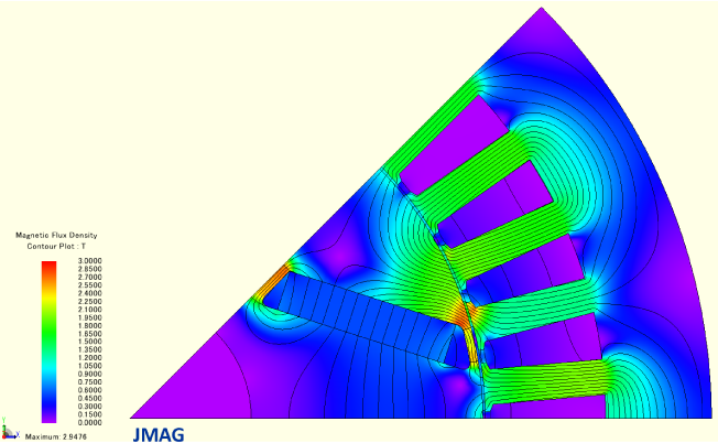
Fig. 1 Flux-plot in a PM brushless synchronous machine under steady-state short-circuit conditions
One of the most important test conditions for a brushless permanent-magnet machine is the steady-state short-circuit condition, sometimes called the ‘sustained’ short-circuit. The term ‘steady-state’ is used here to distinguish this from the sudden short-circuit, which is a transient or dynamic fault condition of equal importance for other reasons not discussed here. As a ‘steady-state’ condition it is amenable to magnetostatic calculation with DC excitation in dq-axes, and this can be done more quickly (with much less data) than the sudden short-circuit.
What is the importance of the steady-state short-circuit condition? An obvious answer is to measure the synchronous inductance Ld, and it is true that a value for Ld can be extracted from the test (or from the corresponding calculation). A previous estimate of Ld is valuable in setting up the steady-state short-circuit test, because the current can be estimated as E/Xd when the frequency (and therefore the speed) is high enough to make the phase resistance negligible in comparison with Xd, [1].
The value of Ld obtained from a steady-state short-circuit condition is not necessarily valid at normal operating points, because of the difference in the pattern of magnetic saturation. Also, the steady-state short-circuit condition gives no information whatsoever about Lq. The value of the steady-state short-circuit test is therefore limited in the determination of the synchronous inductances.
The main value of the steady-state short-circuit condition (by test or by calculation) is to determine the short-circuit current and to check the magnets for demagnetization. While the risk of demagnetization may be greater under transient fault conditions, the steady-state short-circuit condition is relatively simple to test and/or to calculate, and it gives a small amount of valuable data that is useful in ‘calibrating’ the overall fault behaviour of the machine. At normal speeds in all but the smallest machines, the short-circuit current is likely to be much larger than the rated current; and while this has no effect in a magnetostatic calculation it certainly is a hazardous circumstance in the test laboratory.
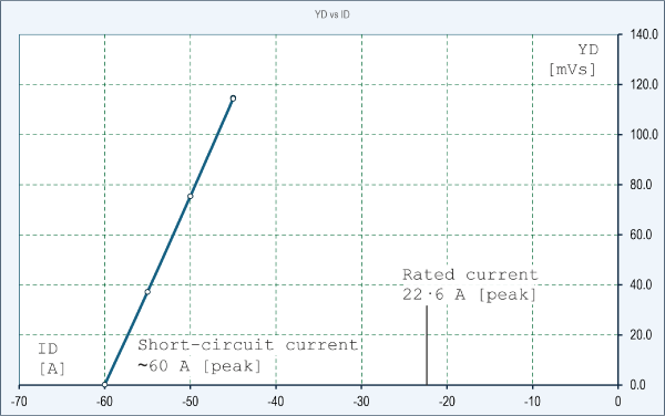
Fig. 2 d-axis flux-linkage vs. d-axis current
It is possible to calculate the short-circuit condition directly with the aid of the finite-element method as part of the design. For fast calculation a magnetostatic finite-element solution is preferable; but unfortunately such calculations are normally formulated with current (or current-density) as an input quantity. For this reason it is necessary to iterate the solution with a range of currents directed along the negative d-axis, and to extrapolate backwards to find the short-circuit current. If resistance is neglected, this current corresponds to the condition where the d-axis flux-linkage YD is zero.
The example in Fig. 2 is for the IPM motor in chapter 7 of the ‘Blue Book’ [2]. It shows a series of finite-element calculations beginning at 45 A [peak] in the negative d-axis, in which the d-axis flux-linkage YD is plotted against the current ID. (Capital letters denote average values taken over one complete electrical cycle, to allow for any variation with rotor position, as discussed in Videos 54 – 56 and Engineer’s Diary No. 76).
The linearity of the graph could be said to be unsurprising, on the grounds that as the operating point approaches short-circuit, the terminal flux-linkage decreases towards zero. It would be natural to think of low flux-linkage as being associated with low flux. We can see from the flux-plot in Fig. 1 at the short-circuit condition, that it would be a little more precise to say that the main flux-path has low flux and is therefore unsaturated, while the leakage paths may be highly saturated. In the main flux-path, the MMF of the magnet is opposed by the MMF of the stator ampere-conductors; but these MMFs combine to force flux through the leakage paths. These conditions are similar to those in transformers and coupled circuits which exhibit similar short-circuit conditions, as discussed in Videos 36 – 41 and Engineer’s Diary No. 70.
The main flux-path in Fig. 1 can be described in terms of the magnet flux, which is swept into the leakage paths on either side of the magnet and fails to cross the air-gap. Equally it can be described in terms of the ‘armature reaction’ flux which crosses the stator in the central part of the pole-piece (either side of the d-axis) but is swept into the same leakage paths and fails to pass through the magnet. The anthropomorphic1 way to say this is that the two MMFs are fighting each other, and neither wins (—or both win, depending on one’s point of view). Some of the ‘armature reaction’ flux actually reverses across the airgap (which it can do, because of the gradient in the MMF across the air-gap). (cf. [5]). The colour-map in Fig. 1 is helpful in interpreting this data, especially with the purple-to-red colour scale which clearly brings out the details.
None of this behaviour is new. It was considered in detail many years ago in connection with line-start motors, in which the risk of demagnetization during the synchronizing ‘pull-in’ process (the final stage in the starting transient) was much worse than in the relatively benign case of a ‘mere’ short-circuit. (See [1], [2‐5]).
Also, since the earliest days of permanent-magnet AC machines there has been a need to reckon with a sustained short-circuit condition that may last indefinitely — for example, in a wind turbine or any other rotating apparatus where the PM machine may be forced to continue rotating even after a short-circuit fault has occurred and the current is not interrupted. The main worry is fire. The obvious way to minimize the risk is to minimize the short-circuit current by designing the machine with a high d-axis synchronous inductance, but that is certain to involve compromises in other important aspects of performance.
A word about the finite-element calculation — The solution in Fig. 1 has 28108 elements, a very small number by modern standards, and the solution time for one point is about one second (too fast to measure with my regular finite-element-solution-timer!) To get such a fast calculation I made use of some basic long-established notions. Although these are well known in the industry, it might be worth discussing them.
- First, the one-eighth section exploits the symmetry of the model to reduce the solution domain by a factor of 8. The solution time is reduced by an even greater factor, possibly as much as 82 or 64. With all the excitation in the d-axis (both the magnet and the armature reaction), the solution is symmetric about the d-axis, which is inclined at 22.5° in Fig. 1. Under normal operating conditions with excitation in both the d- and q-axes, the smallest repeatable model would be one pole; this applies to the stator and the rotor separately, assuming that all poles are identical. This level of symmetry is highest in a machine with integer slots/pole and a fully symmetrical winding (that is, not a consequent-pole winding); it has nothing whatsoever to do with the size of the machine. Machines with fractional slots/pole generally do not have this advantage, and often require the model to span one-half the cross-section or even the whole of it.
- The mesh size in Fig. 1 is defined by a default ‘element size’ of 0.5 mm, against an overall outside diameter of 191.8 mm. No other adjustments were made to the mesh, even in the areas of fine detail such as can be seen in the rotor. Completely automatic settings, on the other hand, produce a mesh size of about 2600 elements; yet the solution for the flux-linkage YD (an integrated or terminal quantity) is almost the same. The main reason for refining the mesh was to give smoother flux-lines for Fig. 1!2
- In spite of (or perhaps because of) the apparent simplicity of this project as an example of finite-element analysis, it is easy to overlook the importance of the nonlinear BH data of the steel parts. The solution has regions of very low and very high flux-density, both of which are of critical importance. These extremes would be expected to test the convergence of the solution process, and in these circumstances the BH data should be smooth and accurate, and it should be extrapolated reliably up to at least 3 T without any discontinuities.
A further enormous reduction in calculation time could have been achieved by using only two or three points in Fig. 2, instead of five. That’s an example of the extreme caution of the old-fashioned engineer — reluctant to extrapolate!
Steady-state short-circuit in other types of machine — Often taken together, the open-circuit test and the short-circuit test (both steady-state and sudden transient) are standard procedures in the testing of many types of electric machine, including DC and AC machines and transformers. For all types of synchronous machine and for the DC machine, iteration of a magnetostatic finite-element solution can be used as described here for the IPM. It is also possible to use a voltage-driven finite-element solution (which is not magnetostatic and requires a transient solver); in this case the short-circuit is defined by a zero-volt condition at the terminals, and the current must be calculated. In setting up this calculation the excitation must of course be defined as part of the problem definition, and for synchronous machines and DC commutator machines the rotor must be rotating with a definite, fixed angular velocity. The reason is that the EMF induced in the armature is speed-dependent and is zero at zero speed. A calculation at zero speed would produce a null result. In the asynchronous induction motor, conditions are somewhat different in that the rotor is generally permanently short-circuited, so there is no point in short-circuiting the armature (stator). What is done instead is the blocked-rotor test, which is a zero-speed condition; with AC excitation on the stator, the complex terminal impedance is used to extract the leakage impedance while the rotor remains short-circuited. (At the same time, the open-circuit test is used to extract the magnetizing reactance). Sudden short-circuit tests are also important with all of these machines, including induction motors (which contribute to the fault level of the power system even though they have no permanent excitation).
Videos 65 and 66 describe the steady-state short-circuit calculation in more detail.
Notes
1 Apologies for the long word! ‘Anthropomorphic’ = ‘like a human’. This word is one of my favourites in technical writing, because it introduces a sense of humour and ‘takes the edge off the seriousness of it all’. Of course MMFs can’t really fight each other, but we often speak of them as though they could. If you like long words, you may prefer to read German: for example Die Einphasenasynchronmotoren (‘single-phase asynchronous motors’) or perhaps Finitelementberechnungszeitgeber.
2 In the early days of finite-element analysis (in the 1970s) it was common to have meshes of 1,000 elements or so, and 28,000 elements would have been a very large number. Yet reliable engineering results were consistently achieved, particularly for integrated or terminal quantities like flux-linkage, torque, etc. The flux-lines in those days were always jagged especially in regions of low mesh-density [6,7]; (also see [8]). Many engineers at the time were resistant to the introduction of numerical methods because of this aspect, because they mistook it for a fundamental lack of accuracy. Ironically, the traditional methods such as the magnetic equivalent circuit method and other methods in the classical theory really were fundamentally inaccurate, even though they served the industry for a century, and they still do.