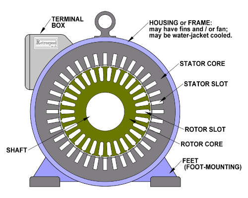
Fig. 1 Induction motor cross-section with 36 stator slots and 30 rotor slots.
The air-gap is enlarged in this image to make it visible.
Why do electric machines have slots?
It is often the case in engineering that someone comes up with an alternative method, usually motivated by a small number of factors. It frequently turns out that the result proves superior to the original method for several reasons, many of which were not foreseen during the early stages of development. Because of this, it is often difficult to say that a certain method was adopted for one peculiar reason. We have to widen our view and consider all the reasons. This is the case with conductors laid in slots. The history is often helpful in making assessments of this type, especially when we go back to the earliest embodiments and patents.
Conductors laid in slots are mechanically supported by the teeth, so that wound cores are robust and integrated as engineering components. The teeth carry the main flux, so the flux-density inside the conductors is generally very small, Fig. 2. The electromagnetic forces are experienced by the teeth and not by the conductors; this is true of the torque as well as of the radial forces. The slot walls surround the coil-sides with a thermally conducting but electrically insulating layer that is important for cooling and safe operation. But these features are operational features. We also have to consider the manufacturing. It is meaningless to say that slotted cores and windings are ‘easier to manufacture’, because it depends on the tooling and the labour requirements and the associated costs of material, energy, scrap, and many other details. It is surely the case that some manufactured windings would seem impossible to make, in the eyes of the pioneers making Gramme ring windings or early slotted armatures. But it is clear that if the advantages are sufficient, there is almost no limit to what can be produced.
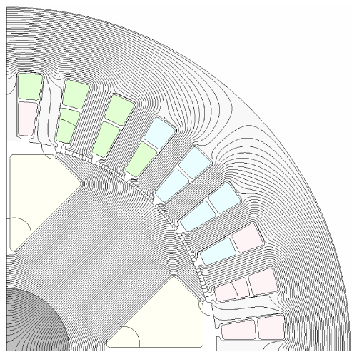
Fig. 2 Flux-lines in a wound-field synchronous machine, showing the concentration of flux in the armature teeth, with low flux-density in the slots. (See [2], Fig. 10.3).
We can say that the reasons for using slotted cores are different for electrical, mechanical, and manufacturing engineers. Each of these specialists has a distinct set of requirements and interests, though of course they are intimately related.
Walmsley [3] asserts that the earliest instance of a slotted armature was the ring armature of Pacinotti (1861) described as a “turned iron ring having the shape of a toothed wheel”, which permitted its sixteen ring coils to be firmly located. Although similar manufacturing considerations — assembly and physical integrity — apply equally to later forms of slotted rotors and stators, Pacinotti’s actual embodiment was hardly suitable for practical industrial designs. But its topology remained the template until the 1870s and perhaps even the 1890s, as seriously useful electric machines were built with rotating armatures having Gramme ring windings with conductors on the surface of the rings (which were generally not laminated).1
Designers at the time were concerned with the transmission of electromagnetic forces from the surface-mounted conductors to the iron ring, (as was Pacinotti). There seems to have been a process of evolution: in some cases surface-mounted conductors were supported by ‘fences’ or wedges let into shallow grooves, with wire binding to resist centrifugal force; Fig. 3.
According to Walmsley [3] the slotted drum armature was introduced by Von Hefner-Alteneck in 1872 and initially manufactured by Siemens Halske. The introduction of slots quickly brought the art close to the arrangements we see today, especially with the use of stacked laminations and punched slots. From the earliest times there was a wide variety of slot shapes, including closed and semi-closed slots, and slots of variable cross-section including asymmetrical slots and even tunnel slots; see Fig. 4. Designers of that era were equally concerned with heat transfer and the cooling efficiency of different configurations, and with the inductance of the coils and windings.
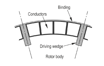
Fig. 3 Use of driving wedges to transmit torque from surface-mounted conductors to the rotor body of an unslotted DC armature (Walmsley, Fig. 842 [3]). Note the binding on the outer surface.
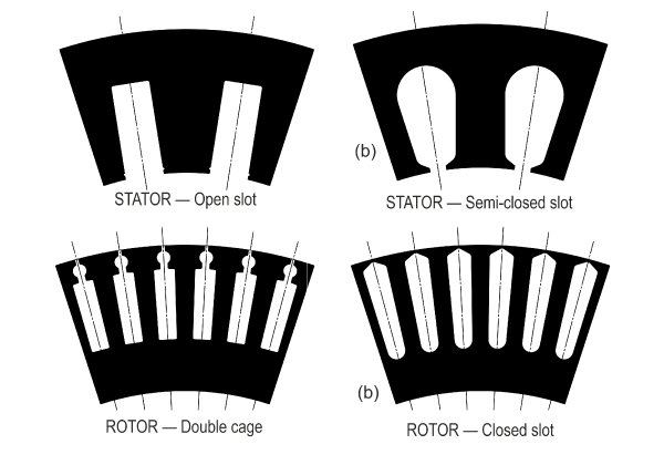
Fig. 4 A selection of slot shapes. There are many more.
When the conductors or coil-sides are fully laid in slots, the problem of transmitting the ‘force on the conductors’ to the rotor or stator body largely disappears. It is remarkable that the theory of the operation and design of electric machines continued to use the ‘BLv’ and ‘BLi’ formulas [2] for the next one hundred years, well into the era of the finite-element method. These formulas (for the EMF induced on a conductor moving in a magnetic field and the force acting on a conductor in a magnetic field) should have disappeared even before the Gramme ring winding; but they persisted even though the magnetic field at the location of the conductors (in the slots) is actually very small, and since it is generally across the slot it produces a force in the radial and not in the desired tangential direction. The ‘BLv’ and ‘BLi’ formulas give practical results if the B refers to a suitably defined component of the air-gap flux-density, and not to the flux-density at the actual location of the conductors; this can be justified theoretically [2] although it is rare to find this justification in textbooks. Many textbooks gloss over these points, which is really not acceptable in the era of finite-element analysis.
When the cross-slot flux is alternating, it causes parasitic losses in the conductors as a result of eddy-currents which are classified as skin effect or proximity effect. It is not the case that conductors laid in slots are immune from these parasitic losses. Indeed in some of the most advanced modern windings (hair-pin windings with open slots) these losses can be a limiting factor on the performance, requiring intricate transpositions and careful design of the conductors themselves (including the use of multiple strands with roving and even Litz wire). These aspects often require the use of sophisticated finite-element analysis in the design process, and specialized CAE programs for optimizing the winding configuration. Even in early times, eddy-current losses in conductors were known and recognized, not only in surface-mounted conductors exposed to the main flux, but also in conductors in slots exposed to slot-leakage flux; [4].
During the evolution from the Gramme ring armature to the drum armature to the slotted drum armature, the importance of coil inductance received more and more attention, partly due to an increase in machine ratings and the challenge of achieving satisfactory commutation. In DC machines the slot-leakage inductance of armature coils is the main component of commutating inductance, which in turn is a key parameter in the commutation process. Putting the coils in slots increases the leakage inductance, and compensating measures would be necessary — such as winding with multiple commutator segments per slot (essentially a means of dividing the winding into sections that do not undergo commutation at the same time), and increasing the number of slots.
In AC machines the slotted armature became the familiar stator, not rotating but stationary. Although commutation with brushes is not involved in the process of operating AC machines from traditional AC power supplies, the leakage inductance of coils in slots has an important role in contributing to the overall leakage inductance and therefore to the level of fault currents, and in the induction motor to the breakdown torque and therefore the operating slip and the efficiency. Leakage inductance is also important in relation to the switching of power-electronic devices in inverters.
In the induction motor the rotor as well as the stator carries AC, and slotted construction with laminations is used with both cage-type and distributed (slip-ring type) windings. In both cases the leakage inductance of the rotor conductors contributes to the overall leakage inductance, more or less in a similar measure to the stator slot-leakage inductance. However, the rotor of a line-fed induction motor has to operate over a wide range of frequency, and it is normal to design the rotor slot-shape to achieve certain frequency-dependent effects such as high starting torque with low operating slip in the deep-bar rotor, the Boucherot rotor, and other forms with single, double, and even triple cages. An enormous variety of rotor slot shapes can be found in the industry, some of them intended to produce thermal improvements as well as electrical features. And in cage-type rotors, closed slots are the norm, so that the conductors can be die-cast under pressure; see Figs. 1 and 4.
Closed slots in induction-motor rotors help to support the conductors against centrifugal loading, but they also increase the leakage inductance and they also make it variable due to saturation of the bridge that lies across the top of the slot. Closed stator slots are also not unknown, and sometimes magnetic slot-wedges are used to reduce cogging torque and surface losses on the rotor caused by the modulation of the air-gap field that arises with normal slotting. The term ‘permeance harmonics’ is sometimes used in this context.
The number of slots is discussed in Videos 3, 8, 26, 27 and 59, and the number of poles in Engineer’s Diary No. 19. Many engineering factors are involved in deciding these numbers, and also manufacturing factors such as the minimum acceptable tooth width.
The common manufacturing process of punching and stacking sheet steel laminations is very old, and it is not difficult to see its practical advantages especially in relation to the handling, transportation, and processing of large quantities of steel (which is generally electrical steel having a composition that gives high permeability and low losses, rather than good machinability). Slots may be punched in a single operation with a large progressive stamping tool, or by sequential notching. The slot shapes are constrained by features and details related to the cost and life of the punching dies, and the process of punching slots leaves a ‘punch zone’ around the slot with impaired magnetic properties that may be restored or partially restored by annealing.
Alternative manufacturing methods include compressed powder-core technology, 3D printing, and (for heavy DC field components only) forging and machining from the solid; but these methods are relatively slow.
In contemplating the neat, robust assembly of coils around a finished stator or rotor, one might naturally ask the question, "Isn’t it difficult to insert the coils in a slotted core, especially a slotted stator where the coils are on the inside?" The answer is that it is indeed difficult: but engineering is difficult! It often evolves into a sophisticated craft that relies on tooling and processes developed over years of invention, refinement, and trial and error. Who is to say that assembling the coils around an unslotted core would be any easier, given that they must be precisely shaped and located, robustly supported, protected against damage, and adequately cooled? If it were ‘easier’ (or more economic) to work without slots we could be sure the industry wouldn’t be using them.
Some classes of machine are much less suited to slotted construction than cylindrical rotary machines: for example, axial-flux machines with disk or wheel armatures and some linear machines and actuators. Some forms of superconducting machines and even machines with high-energy magnets have such high magnetic loading that they can produce relatively high working flux-densities across large air-gaps without the need for magnetic teeth, so that ‘slotless’ air-gap windings can be used. The space ‘vacated’ by the teeth can be used for additional conductors and cooling components, to increase the electric loading (though not without exposing the conductors to the magnetic field).
Most electric machine designers dealing with conventional slotted machines have to reckon with a host of parasitic effects of slotting, including cogging torque, space-harmonics in the flux distribution, surface losses induced by permeance variations at the slot-passing frequency, and many more. Precise calculation of all these effects is now possible with modern finite-element techniques. But while we can claim to analyse the slotted-core winding with accuracy beyond the dreams of our forebears, we can’t claim to have invented slots.
Notes
1 Pacinotti's machine had a commutator with a rolling element rather than sliding brushes. Pacinotti even observed the phenomenon of reluctance torque in the DC commutator motor — rarely ever mentioned in the literature. His description of the conception and working principles of his machine (translated into English in Walmsley [3]) is an exquisite account of the fundamental principles of the DC machine which he invented in 1860. Also note that the Gramme ring winding was commercially successful for many years before the slotted armature; several advantages could be claimed for it, one of which was that when used on the rotor, the radially-directed end-winding conductors could be faced off and used with brushes to act as a commutator. Since the leakage inductance between invidual coils was low, sparking was limited.
References
[1] Hendershot J.R. and Miller T.J.E., Design of Brushless Permanent-Magnet Machines, Motor Design Books LLC, ISBN 978-0-9840687-0-8, 2010, sales@motordesignbooks.com (Green Book)
[2] Hendershot J.R. and Miller T.J.E., Design Studies in Electric Machines, Motor Design Books LLC, ISBN 978-0-9840687-4-6, 2022, (Blue Book)
[3] Walmsley R. M., Electricity in the Service of Man, Cassell, London, 1904.
[4] Field A.B., Eddy Currents in Large Slot-Wound Conductors, 22nd Annual Convention of the American Institute of Electrical Engineers, Asheville, N.C., U.S.A., June 19-23, 1905, pp. 761–788.
See also
Alger P.L., Induction Machines, Their Behavior and Uses, Second Edition, Gordon and Breach, New York, 1970.
Veinott C.G., Theory and design of small induction motors, McGraw-Hill, 1959.
Kostenko M. and Piotrovsky L., Electric Machines, MIR Publishers, 1974.
Clayton A.E and Hancock N.N., The Performance and Design of Direct Current Machines, 3rd edn., Pitman, London, 1959-66