In this phase, component requirements are specified from a system design based on the required performance. In other words, the design is broken down to requirement specifications of the motor.
Traditionally motor specifications have been determined using experience and rule-based processes. However we determine motor specifications meeting system requirements with heavy use of simulations. Simulations make it possible to investigate a very large design space at high speed. This allows a design space to be systematically narrowed down without missing any cases.
In the example on the right, drive motor and drive requirements are determined from EV requirements. The power flow of candidate motors is investigated after determining the type of motor and the output based on system requirements. The motor type is selected using evaluations of the required maximum torque and maximum power after basic motor requirements have been determined. An I-shaped IPM motor is selected for reasons of high efficiency and low magnet quantity (low price).
Evaluating motor geometries and configurations at system design allows efficient development with less rework.
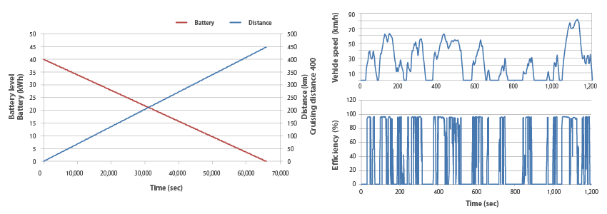
Validation of cruising distance
When using a motor designed with a basic design, the required cruising distance (400 km) with the assumed battery capacity (40 kWh) was confirmed. The maximum running distance is obtained by calculating the power consumption from variations in efficiency obtained from JC08 mode running simulations.
Vibration reduction measures/Mode running simulation
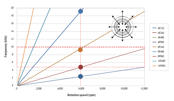
Vibration reduction measures
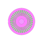
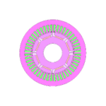
Since the frequency range where measures are required is 5-10 kHz, choose the number of poles and the number of slots so that the frequency of the electromagnetic excitation force generated by the motor does not overlap this range. In order to realize a low noise level at a vehicle speed of 100 km/h, the frequency of the excitation force at a motor rotation speed of 6,000 rpm used for that speed range is investigated. When the number of poles and the number of slots is 4 poles and 24 slots, 4 poles and 48 slots, 8 poles and 24 slots, the excitation force frequency falls within 5-10 kHz, so these combinations are excluded.
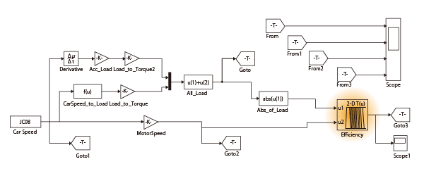
JC08 mode running simulation
Using an efficiency map for a motor designed with a basic design, variations in efficiency when running in JC08 mode are obtained using Simulink.
Design selection based on maximum output, maximum torque, and maximum efficiency
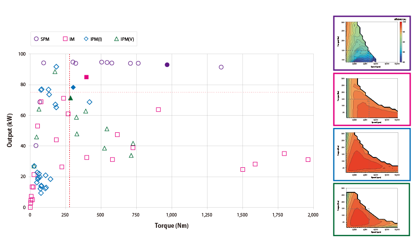
Parametric analysis is performed while varying the motor type, the number of poles, the number of slots, the number of turns, and the rotor diameter, and the maximum output and maximum torque are evaluated to narrow down possible designs (left figure). IPM (IPM (V)) having a V-shaped magnet arrangement could not meet the requirements. Evaluating the efficiency map (right) for the three types of cases that meet the requirements, the I-shaped IPM motor with the widest ranging maximum efficiency in the drive range (~ 5,000 rpm, ~ 150 Nm) used in JC08 mode, with 8 poles, 48 slots, and 5 turns was chosen.
Related materials
Application Catalog
In this example, the use of JMAG-RT Viewer to create efficiency maps for three-phase induction motors when drive temperatures change....
In this example, an efficiency map of an IPM motor is created and the loss ratios at each operating point are evaluated....
Leaflet

Within upstream system designs in a development process, elements that satisfy motor requirements are all roughly determined. This includes the rotor ...
JMAG-Express is a motor design tool that instantly calculates unique motor characteristics in order to output design specifications to meet design req...

