All electric machines use wire — usually of copper, but sometimes of aluminium. The electrical resistance \(R\) determines the \(I^2 R\) loss (Joule loss) in each winding when the RMS current is \(I\) amperes. Since this loss is usually the largest component of the total loss, it has a strong effect on the efficiency, so it is clearly important to estimate \(R\) as accurately as possible. Although “resistance” is a simple concept, it is not easy to determine an accurate value in design calculations.
Similar considerations apply to the weight of wire, which is an important component of the manufacturing cost.
The simple formula for resistance is Resistivity × Length / Area, or \(R = \rho l/a\), where \( \rho \) is the resistivity, \(l\) is the length of conductor, and \(a\) is its cross-sectional area. If the cross-section is assumed to be perfectly circular with diameter \(d\), then \(a = πd^2/4\).
The simple formula for weight is \(W = \delta la \), where \(\delta\) is the mass density. Of course, these formulae need to be modified to take into account the number of parallel paths, the number of phases, and the lengths of interconnectors; but we will set these factors aside here.
From the equations it appears that the ratio \(W/R\) is proportional to \(d^4\), so that if both the weight and the resistance are to be calculated accurately, \(d\) must be known with great precision. Fig. 1 shows some effects of uncertainty in the wire diameter \(d\). In the table on the left, the variation in \(d^4\) falls within the range from -2.9% to +4.5% even for normal catalogue variations or tolerances in the wire gauge.
The table on the right shows typical measurements of bare wire diameter, using methods that would be convenient for a spot-check in the factory, and here again these is some variation between methods. If the true diameter is 0.415 mm, the error in \(W/R\) estimated using the nominal value 0.425 mm will be about 4 × 2.35 = 10%. This means, for example, that if the weight is calculated accurately the resistance will have an error of 10%, or vice-versa. (The weight will be accurate only if the error in \(d^2\) is compensated by an opposite error in the wire length \(l\)). It is by no means a simple matter to resolve the uncertainties associated with errors in wire diameter, even when the wire cross-section is perfectly circular.
Fig. 2 shows a test fixture for measuring samples of magnet wire. A sample of about 10m length is wound several times around two bollards, and its ends are connected to terminals A and B. The resistance \(R\) is measured with a digital ohm-meter, and the weight \(W\) is measured with a digital scale. This type of fixture can be used for quality checks on bought wire, or for checks on design calculations.
For example, the quotient \(W/R\) gives the square of the cross-sectional area \(a^2\), if the resistivity and density are known. Alternatively the product \(RW\) gives the square of the length of wire \(l^2\). This product can be used to check the mean turn length when \(W\) and \(R\) are measured on a sample machine.
In precise design calculations, we are faced with several other uncertainties. The temperature of the wire in a machine winding is not uniform, and since the resistivity varies nearly 0.4% for every centigrade degree, this non-uniformity can introduce small uncertainties. The length of wire is extremely difficult to predict accurately in design calculations, because of the complex “lay-up” of the turns especially in the end-windings. In some machines the wire stretches during the winding process, resulting in a reduction in area \(a\), an increase in length \(l\), and even a slight increase in resistivity \( \rho \). Sometimes we cannot be completely certain about the degree of uniformity in the wire cross-section area. These factors help to explain why engineers usually use “ohms per km” for a given wire gauge, instead of ohm-m; and “kg/km” instead of kg/m3. In other words, we use real engineering data rather than textbook physical constants of materials. We can also understand the term “temperature rise by resistance”, which concerns the estimation of average winding temperature from the terminal resistance.
Is there a simple message to take away from this discussion? Yes! Always weigh your windings. Knowing \(R\) is not enough. We need \(W\) also. When we know both \(R\) and \(W\) we have a much better understanding. And maybe a suitable mnemonic would be \(R\)ei\(W\)a ( 令和 ) !
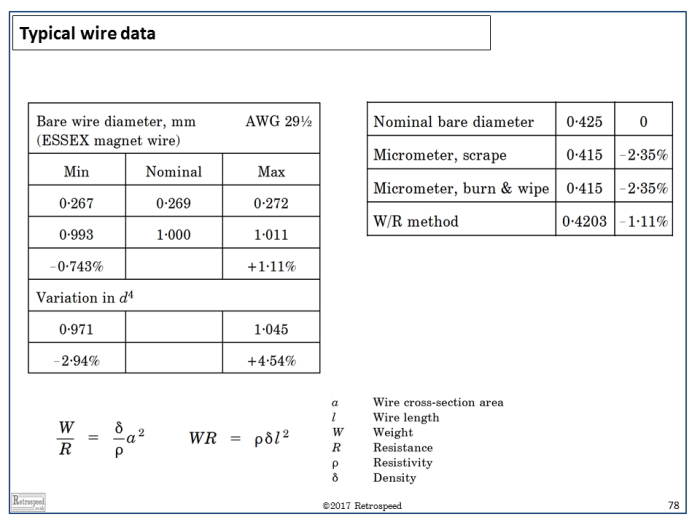 Fig. 1 Wire measurements in the factory
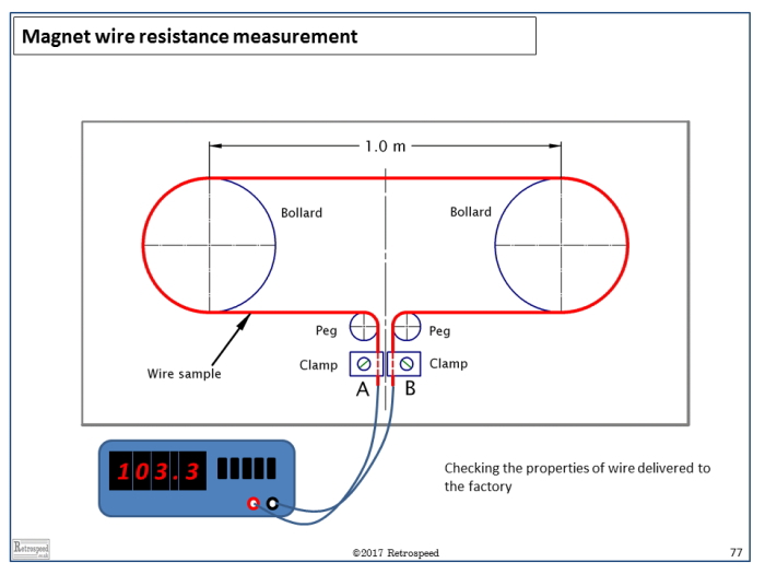 Fig. 2 Measuring wire length and resistance
ご意見ご感想をお聞かせください。皆さま方からの貴重なお声として、今後の参考にさせていただきます。
なお、ご質問に関する回答は致しかねますので、あらかじめご了承ください。

