The IPM or interior permanent-magnet motor started its history as a line-start motor in the 1950s. At that time Alnico magnets were the best available, but their low coercivity meant low resistance to demagnetization, and this was a serious limitation because of the huge demagnetizing MMF experienced during synchronization (or even worse during pull-out due to overload). In the late 1970s several line-start PM motors emerged with rectangular high-coercivity rare-earth magnets which could be magnetized through the short dimension, giving rise to the iconic concept shown at B in the figure. This geometry can be attributed to Reliance Electric in the United States, but many other concepts were introduced during that period, some using ferrite magnets and some using arc-shaped magnets (Hitachi); but in all cases the essential topology was that of an induction-motor rotor (A) with magnets inside the cast squirrel-cage. We thus have the beginnings of the evolution of the IPM, starting from the induction motor.
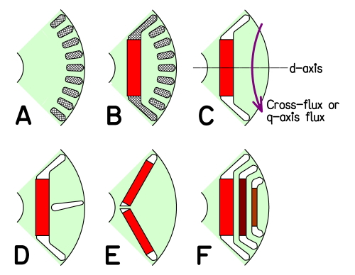
Although the line-start motor has continued to evolve, a truly epoch-making development soon emerged with the removal of the squirrel-cage (C), leaving a motor which has no line-start capability. This motor requires an AC supply whose frequency is controlled so that its phase is synchronized with the rotor position, while its amplitude is regulated to maintain the correct flux-level — in other words, an inverter. Fortunately, in the 1970s and 1980s huge efforts were being made to develop inverters for adjustable-speed operation of induction motors, and the IPM certainly benefitted from this, even though its control requirements were slightly different. At first the inverters were 6-step inverters with cumbersome voltage-regulating stages (such as phase-controlled rectifiers), but by the 1980s the PWM current-regulated inverter was becoming established, thanks to advances in power-electronic devices, microelectronic control technology, and the principle of field-oriented control introduced by Siemens and attributed to Felix Blaschke. This type of inverter, together with a shaft-position transducer to help the synchronization function, opened the way for the development of the IPM. But another huge boost arrived in the mid-1980s with the introduction of Neodymium-Iron Boron magnets, promising lower cost for high-energy magnets which were expected to compete with Cobalt-Samarium.
So from concept C there has been a rich story of evolution in the details of rotor geometry, and in simple terms we will discuss a few common ideas here. In C the magnet flux passes essentially in the horizontal direction, defining the d-axis (direct axis) as the centre-line of the magnet or rotor pole. But the stator current produces a secondary component of flux — armature reaction — which tends to flow across the pole, more or less in the vertical direction in the confines of the diagram. The magnet flux passes through the airgap and through the magnet itself, which has a low permeability, and this produces a low inductance “seen” from the stator winding along the d-axis. But the cross-magnetizing armature-reaction flux only has to cross the airgap, and this produces a high inductance “seen” from the stator winding along the q-axis or quadrature-axis. Consequently the so-called q-axis flux can be quite large.
The difference in “inductivity” between the d-axis and the q-axis is an instance of saliency and it gives rise to the possibility of “reluctance torque” when the axis of MMF of the stator winding is suitably adjusted. The greater the saliency, the greater the reluctance torque per ampere of q-axis current. Unfortunately the high “inductivity” of the q-axis flux-path leads to rapid saturation of the soft iron rotor pole-pieces, and this decreases the saliency and the reluctance torque. To prevent this, slits (D) are sometimes introduced to present a barrier to the q-axis flux, but of course in reducing saturation they also reduce the q-axis flux and inductance and also the reluctance torque; so their main effect is to linearize the torque/current relationship to a certain degree.
The cross-magnetizing flux reinforces the magnet flux on one side of the pole, and depletes it on the other side, so the saturation is greater on one side. This gives rise to the notion that the slits could be tilted to try to balance the effects, but of course this can be considered only for motors operating in one “quadrant” of the torque/speed diagram.
A more common design idea is to use a V-shaped magnet, (E). This widens the path for the q-axis flux and reduces the tendency to saturate; it also slightly enlarges the magnet pole-face area (producing more magnet flux), but it also tends to depress the operating point of the magnet on its BH demagnetization characteristic. The magnets may also become thinner, which exacerbates this effect and may increase the risk of demagnetization during overloads.
The quest for reluctance torque is closely associated with the objective of a wide speed range at constant power, and in simple terms this can be understood by combining the pure PM motor with a pure reluctance motor to create a hybrid structure, (F). The synchronous reluctance motor has an inverse torque/speed characteristic while the PM motor has a “constant torque” characteristic which limits the maximum speed when the supply voltage is fixed. The reluctance motor in F can be thought of as the result of removing all the magnets, leaving flux-guides for q-axis flux and flux-barriers for d-axis flux (keeping the same definition of d- and q-axes as before). In the hybrid motor, the flux-barriers house the magnets.
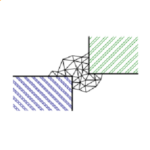
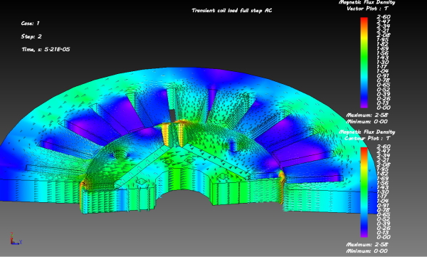
Such hybrid structures are now common, especially in automotive traction motors. They have been developed to a fantastic level of complexity, incorporating all the ideas in D,E, and F, as well as many more. In some cases the magnets are not all of the same material, and of course the mechanical complexity is considerable. It is obvious that the design and analysis of such sophisticated machines requires sophisticated CAE tools, as we can see in the finite-element image (courtesy of Yves Thiolière, Powersys).
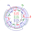
Maybe I should have mentioned that the stators and windings of all the machines in the diagram (including the induction motor) are essentially the same, and so are the inverters. It is often helpful to consider all these machines as members of the family of AC drives.
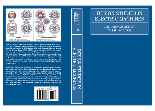
More detail can be found in the “Green Book”, Design of Brushless Permanent-Magnet Machines”, available in Japanese translation from MS-TECH in Tokyo.
ご意見ご感想をお聞かせください。皆さま方からの貴重なお声として、今後の参考にさせていただきます。
なお、ご質問に関する回答は致しかねますので、あらかじめご了承ください。

