How should we synthesize a suitable winding layout for an AC brushless PM motor?
While the properties of existing windings can easily be analysed using a spreadsheet program, it is not so obvious to create a new winding layout from scratch. So here is an example of a systematic approach that will work in many cases.
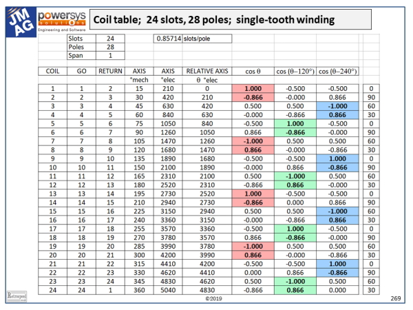
The example has 24 slots and 28 poles. Thus the slots/pole = 0.857, and since this is close to 1 we are clearly going to use single-turn coils. The table shows 24 coils. In practice they are all wound in the same direction with a span of +1, their polarities being fixed by the interconnections; but here we will show the polarities by means of the signs or directions of the ampere-conductors rather than the directions followed in the winding process. The arrowheads on the end-windings also show these directions. With this method we lose the important practical detail of the interconnectors, but we obtain a compact diagram.
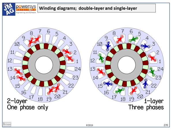
We need to describe the properties of each coil. Taking coil 1 as an example, it has a “go” slot (1) and with a span of +1 it has a “return” slot (2). We can see this in the diagram, in which the numbers are the slot-numbers. Its axis is at 15° from the horizontal, and in electrical degrees this is 15 × 28/2 = 210°. Taking coil 1 as the reference, we find the relative axis angle of every other coil, in electrical degrees. For each coil this angle is denoted \(\theta\).
In the next three columns we calculate cos(\(\theta\)), cos(\(\theta – \)120°), and cos(\(\theta + \)120°). In effect, these cosine functions project the MMF (magnetomotive force) axis of each coil along three axes associated with the three phases. Thus for example coil 1 is clearly aligned with phase 1 (red) while coil 3 is reverse-aligned with phase 3 (blue).
If we follow this logic for all the coils which are perfectly aligned with one of the phase axes, we will end up with the single-layer winding on the right-hand side of the winding diagram (1 coil-side per slot). Note that in each phase, the polarities of successive coils are reversed; for example coil 1 goes from slot 1 to slot 2 and belongs to the red phase, but coil 7 goes in the reverse direction from slot 8 to slot 7. As we have said, in practice the coils would not be wound in opposite directions, but connected in opposite directions.
In the table we can see that we have accounted for all the odd-numbered coils, but what about the even-numbered coils? They can be paired with the adjacent odd-numbered coils but only by connecting them in series, because of the 0.866 cosine factor. (There is still the possibility of up to 4 parallel paths in each phase). When this is done, we get the double-layer winding in the left-hand diagram (2 coil-sides per slot), although only one phase is shown.
The reader is encouraged to create a spreadsheet to do this job. It will quickly be found that the technique is a powerful one for synthesizing windings — not only single-tooth windings but other, more general windings. Note that the coil polarities fall out naturally according to the signs of the cosine functions, while the coils are clustered into pole-groups by associating sets of coils with the largest cosine factors together. For example, in the red phase in the double-layer diagram, a pole-group is naturally formed by coils 1 and 2 in the table. Having one’s own spreadsheet is a good way to explore the properties of windings.
In general the process involves assigning each coil to one of the three phases according to the relative magnitudes of the three cosine functions, taking the sign into account to determine the connection polarity. This assignment is not unique, but allows room for judgement and some flexibility. If you’re adventurous, write yourself a procedure to draw the windings in a CAD program and to plot the MMF vectors in the complex plane! A really ambitious project would be to devise a logical way of selecting the best winding from all the feasible ones. This is not a trivial challenge: the “best” winding might be defined in terms of its harmonic properties (EMF waveform and differential leakage inductance), or in terms of the bulk and complexity of the interconnectors.
The coil table can also be used as the basis of a primitive inductance matrix which can be transformed by means of connection matrices to generate the self and mutual inductances of the fully connected three-phase winding, as taught by Gabriel Kron. Connection matrices are the mathematical expression of the process of wiring up the coils in the required circuits and phases with the correct polarities. They are essential for mapping the winding layout to the resulting electrical circuit diagram of the machine.
A natural extension of the table is to add the winding factors including the harmonic winding factors, from which more advanced properties can be obtained: for example, the Görges diagram and from it the associated differential leakage coefficient.
The rightmost column in the table shows the modulus of each coil axis angle \(\theta\) and 120°. The zeroes pick out the “starts” of each pole-group, according to the respective phases. With a little thought, you should be able to work out the direction of rotation for a given phase sequence, such as red-green-blue. (It’s anti-clockwise).
The “heuristic” method described here does not guarantee that a suitable winding is feasible, with the given numbers of slots, poles, and phases. The theory of the feasibility of windings is a complex subject going back 100 years or more, with famous papers by S.P. Smith, W. Kauders, and many others; and books such as Heller and Hamata.
Finally a test! What are the winding factors for the working harmonic (the 14th) in the two windings in the diagram? (Answer: 0.9330 in the left-hand diagram, 0.9659 in the right-hand diagram. Don’t forget the pitch factor!)

