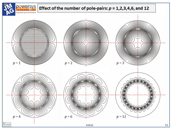
The figure shows the some of the effects of pole-number on the magnetic field in a rotary electrical machine. It is a highly idealised figure: the winding is a current-sheet in the middle of the air-gap between two cylindrical iron cores of high permeability. The current flows in the axial direction and it is sinusoidally distributed around the circumference of the winding, with 2p poles. There are no end-effects, no slots, no salient poles, and no magnets. [See Foord and Miller, 2016, and Hughes and Miller, 1977].
The winding represents the ideal notion of a sinusoidally-distributed winding with 2p poles. It could have just one phase, in which case the magnetic field would be stationary. With DC current in the winding, the field would also be constant. With AC current, the field alternates at the AC frequency \(f\), and its time-waveform at any point is a sinewave.
The model can also represent a polyphase winding having m phases. If the m phase currents are sinusoidal and balanced (equal in amplitude and evenly spaced by 360/m deg. in time-phase), the field rotates at the so-called synchronous speed, \(f\)/p revolutions per second.
Having set out these preliminaries, we can ask what kind of machine is covered by this model? The answer is any non-salient-pole AC machine, which includes the induction motor and the surface-magnet brushless AC motor. It also includes the cylindrical-rotor synchronous machine. In fact the original analysis [Hughes and Miller, 1977; and Miller and Hughes, 1977] was done for superconducting AC generators, in which the rotor is completely non-magnetic; the intention was to explain the fundamental reasons for the low per-unit synchronous reactance of these machines.
Many of the most important practical effects of pole-number can be seen in the Figure. Starting with p = 1, the field of the 2-pole machine is uniform inside the rotor. It crosses the shaft and may cause problems with eddy-currents. In surface-magnet motors operating with PWM inverters, the modulation of the terminal flux-linkage at the PWM frequency propagates right through the rotor, and may cause eddy-current losses deep inside the rotor and the shaft.
As the pole-number increases, the magnetic field in the centre of the rotor decreases quite rapidly, leaving a void with little or no flux. This is what permits the use of hollowed-out ‘spider’ construction in large multi-pole machines like wind-turbines. At the same time, the flux/pole decreases, so that the radial depth of the stator yoke can be proportionally smaller when the pole-number is higher. In other words, the ‘split ratio’ (rotor/stator diameter ratio) increases with pole-number.
Also as the pole-number increases, if the ‘electric loading’ remains constant (that is, the RMS amperes per radian around the circumference) the total number of ampere-conductors per pole decreases in inverse proportion to the pole number. Consequently there is less MMF available to excite the flux. Conversely, for a given flux-density at the air-gap, the magnetizing current must increase with increasing pole-number. This is one reason why the power-factor of induction motors tends to decrease with increasing pole-number.
The particular method of analysis treats the winding in terms of just one space-harmonic. Real windings are made with discrete coil-sides whose angular positions are often treated as being concentrated at the respective slot-openings at the surface of an unslotted stator or rotor. Real windings are divided into pole-groups and they may be wound with fractional values of slots/pole. For all these reasons they produce a rich spectrum of space-harmonic fields, each one of which could be represented by a sinusoidal current-sheet as in the Figure.
When the air-gap is very narrow compared with the winding radius, the somewhat complex mathematical formulas for the fields and inductances reduce to much simpler forms, which are identical to those found in classical textbooks for narrow-gap machines. These formulas generally assume that the flux passes radially without attenuation across the gap. On the other hand, when the air-gap is large, or when either the rotor or stator core is non-magnetic, the formulas provide insight into the behaviour of fields of different harmonic pole-number. This is especially important in surface-magnet brushless machines because the space-harmonic components of the winding distribution interact with the time-harmonics in the current waveform (including the fundamental) to produce eddy-current losses in the rotor. The harmonic pole-number strongly influences the radial attenuation and depth of penetration of these parasitic field components, (as well as their speeds of rotation).
The mathematics used in the Hughes & Miller papers is closely related to the later work of Z.Q.Zhu and Z.P. Xia et al in the analysis of permanent-magnet motors and Halbach magnet arrays [easily found in IEEE Xplore®], and to the much earlier work of Bernard Hague [1929]. All three approaches solve the Laplace or Poisson equation by separation of the variables. The main differences between them arise in the modelling of the excitation source. Hughes and Miller used current-sheets of sinusoidally distributed linear current-density; Xia and Zhu used distributed magnetization vectors and other methods; while Hague used a collection of filamentary conductors on the surfaces of the smooth rotor and stator cylinders. Hague’s analysis is historically interesting because it leads directly to the harmonic winding factors and the classical formulation of harmonic leakage reactance. In 1929 the analysis would have been relevant to a wider class of machines, including DC and AC commutator machines with distributed field windings and rotary converters. Sadly (perhaps), these fascinating machines have long been displaced by power-electronic converters. But the mathematical theory lives on, to enlighten our modern practices.
The solution of Laplace’s equation used for the flux-plots in the Figure can be written in terms of a scalar potential or a vector potential, and in both cases the flux-lines can be expressed as loci in terms of closed-form expressions. These loci can be plotted with virtually unlimited precision, producing a very smooth result with no evidence of the discretization or ‘stair-stepping’ that arises with the finite-element method. (In the early days of numerical analysis, this ‘jaggedness’ in the flux-lines was disconcerting and even prompted hostility towards the finite-element method in the columns of learned-society journals). Alternatively they can be plotted using the method of ‘marching squares’, which was actually used in this case. Because of the orthogonality of the flux-lines (‘stream lines’) and the equipotentials, the loci for the equipotentials can also be derived using the Cauchy-Riemann conditions and plotted using the same methods. They are omitted here, because the diagrams would become too ‘busy’ if they were included. Maybe in a future diary, we can see some.
Foord T.R. and Miller T.J.E., Laplacian Fields: Analogies, Algorithms and Applications, Retrospeed publishing, 2016, 231pp. Print-on-demand available from the author.
Hughes A. and Miller T.J.E. [1977] Analysis of fields and inductances in air-cored and iron-cored synchronous machines. IEE Proceedings 124, 121-128.
Miller T.J.E. and Hughes A. [1977] Comparative design and performance analysis of air-cored and iron-cored synchronous machines. IEE Proceedings 124, 127-132.
関連記事
ご意見ご感想をお聞かせください。皆さま方からの貴重なお声として、今後の参考にさせていただきます。
なお、ご質問に関する回答は致しかねますので、あらかじめご了承ください。

![ミラー先生のモータ設計学び直しWEBセミナー [毎月更新]](/jp/wp-content/uploads/sites/5/engineers_diary/bn_prof.miller-150x150.png)


