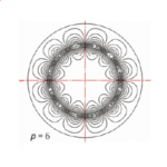
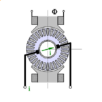
Sometimes I wonder why we don’t see equipotentials in finite-element flux-plots. Strictly speaking, at least in 2D flux-plots, we generally do see them because the flux-lines are contours of constant values of the vector-potential. But here I’m referring to the contours of the orthogonal conjugate functions which cross the flux-lines at right-angles to make the so-called curvilinear squares.
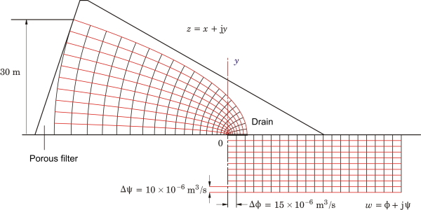 Fig. 1 Seepage under an earth dam
Fig. 1 gives an example. It represents the analysis of the viscous flow of ground-water through a porous dam. The ‘head’ or local pressure is controlled by Darcy’s law, and when this is combined with the continuity equation (zero divergence), we get Laplace’s equation. Before going any further, readers should be reassured that the relevant porosity (the ‘average volume porosity’ is low enough to keep the flow to a trickle. However, earth dams are not totally impervious and so the seepage must be understood.
This example illustrates the solution of Laplace’s equation. We can see this in Fig. 1. On the right-hand side is plotted a rectangular grid called a ‘flow-net’, which depicts a self-evident (or easily calculated) solution of Laplace’s equation in a simple rectangular geometry. The flow is from left to right, and is represented by the red ‘stream-lines’ (flux lines). Between any pair of red lines we have the same quantity of flow in cubic metres/second. The black lines represent equipotentials of local pressure or ‘head’, and the head decreases from left to right in equal increments between successive equipotentials. It is important to accept that this diagram represents a self-evident solution of Laplace’s equation, although it is easy to prove in case one is doubtful!
The rectangular flow-net is represented by a complex function \(w = \phi + j \psi \), in which \( \phi \) represents the head and \( \psi \) the rate of flow. Both \( \phi \) and \( \psi \) satisfy Laplace’s equation and they are related to one another by the Cauchy-Riemann conditions, so that if we know one of them we can calculate the other (within an arbitrary constant). The function \(w\) is plotted with a negative imaginary part in Fig. 1, to keep it clear of the left-hand diagram.
Now the solution for the flow in the actual dam is obtained by means of the conformal transformation \(z = Cw^2\). Using this formula, equipotentials and stream-lines are mapped from the w-plane on the right to the z-plane on the left, where they fit the profile of the dam, at least approximately. The crescent-shaped area on the left is generally filled with a porous rock filter, so the approximation is improved.
The solution is completed by finding suitable scale-factors which determine the value of \(C\). An important part of this is the application of physical boundary conditions, but once the solution is correctly scaled it becomes possible to perform integrals. In this case the integral of the total flow determines the required capacity of a drain which is fitted just to the right of the origin in Fig. 1.
This simple example shows all the essentials of the method of conformal transformation, which has been (and still is) widely used in the solution of Laplace’s equation. We can see how the equipotentials and flux-lines are both integral to the method, and how the appearance of the curvilinear squares provides a visual check on the result.
We can perhaps also begin to see why the equipotentials are often missing in modern finite-element solutions, even though they could be produced if necessary. First, the finite-element method solves the field equations numerically in terms of a single potential function (generally the vector potential), and not in terms of two conjugate scalar potentials. So the equipotentials in Fig. 1 would need to be constructed as a separate process after the solution. Secondly, the finite-element solution applies in non-linear materials which may even be non-isotropic and inhomogeneous. The method of conformal transformation is essentially linear, so it does not work in these regions and in fact it relies on boundaries with ideal properties (such as infinite permeability for iron surfaces). In such materials the map of equipotentials may not be helpful because of extreme gradients near boundaries, and these gradients will generally be most extreme in regions which are of interest for other reasons — in electric machines, for example, core losses may be the most important consideration. It becomes clear why there is so much emphasis in finite-element programs on colour-maps of flux-density or loss-density, which are unobtainable by the method of conformal transformation.
So I don’t think we have a strong case to go to the finite-element developers and ask for the equipotentials to be included in flux-plots, except possibly in the air regions of electrical machines (around the air-gap and the teeth and magnets, for example), or in open regions far from the main surfaces. I must say I would be a little nervous in making this request. I might get a reply such as this : ‘We’ve given you nonlinear time-dependent solutions in complex geometries far beyond the scope of your smelly old conformal transformation method, with core losses and thermal and stress calculations besides. And you want equipotentials as well?’
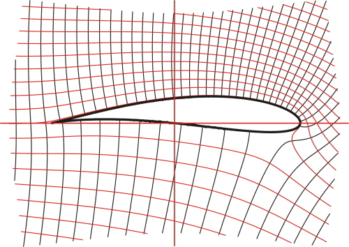 Fig. 2 Stream-line flow around a Joukowski aerofoil, with circulation
But don’t let’s leave it there. The seepage problem is only one example of many applications of conformal transformation, and the transformation itself \(z = Cw^2\) is a very simple one. In other cases the transformation functions are more complicated, and sometimes transformations are cascaded or concatenated through several stages. The famous Schwarz-Christoffel transformation is an example, used by Carter in 1901 to calculate the effective air-gap in an electric machine with slots facing the air-gap.
We can perhaps bring our discussion to a close with Fig. 2, which is an example of the analysis of air-flow over an aerofoil. This example uses a series of transformations beginning with the calculable inviscid flow around a circular cylinder, with the addition of a ‘circulation’ term to provide lift, which is essentially the pressure differential between the upper and lower surfaces. The aerofoil in Fig. 2 has a definite shape obtained by a particular conformal transformation of a circle, and it is named after its inventor N.Y. Joukowski (or Zhukovski; 1847-1921). This work was done at the dawn of the era of powered flight.
The mathematics of the method of conformal transformation is elegant and could be described as beautiful (although students may dispute that). But it is difficult, and every new problem requires mathematical invention and manipulation — by whom? By you, the engineer! So it’s not difficult to see why the finite-element method is generally preferred, with or without equipotentials.
Reference : T.R. Foord and T.J.E. Miller, Laplacian Fields: Analogies, Algorithms and Applications, 2016. Originally written by Dr. Thomas Foord and completed after his death in 2010 (with program illustrations and extensions in PowerBasic®) by T.J.E.M. Unpublished; but print copies can be made available by arrangement, at cost. The mathematics of these and other examples is given in full, with extensive references.

