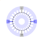
The single-phase induction motor is one of the most common electric motors. For many years the annual production levels world-wide have been 100,000,000 in round numbers. You can find it in refrigerator compressors, but also in many other household appliances and small industrial equipment. It is also very old, dating back to the 1890s.
The pure single-phase motor cannot produce a rotating magnetic field at zero speed, and is therefore not self-starting. It normally has a capacitor winding for starting purposes; but once it is running it performs remarkably well without the capacitor winding, which in many arrangements is disconnected as the motor approaches its running speed.
Recently an old friend contacted me to discuss some aspects of this motor. Years ago, I asked him how many motors were produced each year to his design, and the answer was “several million”. It’s humbling to hear that. If a pop-star sells that many records, he or she becomes rich and famous, but the same thing rarely happens to engineers.
A particular observation with the single-phase motor is that if the capacitor winding is disconnected while the motor is running at no-load near synchronous speed, the current increases significantly. To be precise, the magnetizing current in the main phase winding becomes almost twice the value it has when the motor is running as a balanced two-phase motor at no-load. Although this is recognized in the classic texts, it is rare to find a complete explanation in plain words. I would like to offer one here, and then go on to discuss the extraordinary level of abstract thinking that underlies the theory of the single-phase induction motor.
At no-load with the rotor rotating at synchronous speed, we invoke the double-revolving-field theory to argue that the backward-rotating field is practically zero. It is completely suppressed by the currents induced in the rotor at the relatively high frequency of double the line frequency. (The slip relative to the backward field is equal to 2). If the voltage imposed on the main winding is 1 per-unit (1 p.u.), there must be a forward-rotating field of 1 p.u. In a balanced 2-phase motor, according to the cross-field theory, this rotating field requires balanced magnetizing currents I1 in the main axis and +jI1 in the cross axis. Here j is the phasor operator meaning a phase advance of 90° in time, and all currents are phasor values of sinusoidal currents at line frequency.
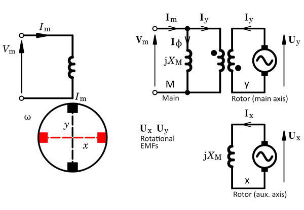
To sustain the pure forward-rotating field we need the magnetizing currents to remain unchanged in both axes when the capacitor winding is disconnected. In the main axis the net magnetizing current is Im − Iy, that is, the difference between the main winding current and the current induced in the rotor by transformer action in the main axis. In the cross-field axis the magnetizing current +jI1 must be supplied by current in the rotor; and with no mutual coupling between the two axes, this current must be excited by a rotational EMF Ux proportional to the main-axis flux and I1. This is often attributed to the “flux-cutting” action, and it is a perfectly natural product of Faraday’s law.
Many of the classic texts written over the last 120 years finish their “plain words” explanation at this point, and move on with a mathematical model. The plain-words account can be completed as follows. If I1 in the main axis produces jI1 in the cross-field axis, it follows that jI1 in the cross-field axis produces −j2I1 = +I1 in the rotor in the main axis, by a similar process with a rotational EMF Uy. The main-axis rotor current is Iy, so we have I1 = Iy = Im − Iy, from which it follows that Im = 2I1 = 2Iy. The main-axis rotor current driven by the rotational EMF from the cross-axis flux is transformer-coupled to the main-axis stator circuit. Because of the linkage between the x and y circuits through the rotational EMFs, we can say that the main winding ends up supplying the excitation for both axes, and it doubles in the process of doing so.
In this discussion we have used both the double-revolving-field theory and the cross-field theory. There is always discussion about which of these theories is easier to visualize physically. Both theories rely on abstract concepts: neither is limited to a purely physical description of observed processes. The revolving-field theory starts with the abstract concept of the resolution of a pulsating sine-distributed field into two rotating components of half amplitude, rotating in opposite directions at synchronous speed. Once this has been grasped, most of the remaining theory follows from that of the polyphase motor, and no further special abstract concepts are needed.
The cross-field theory represents the rotor by two orthogonal windings (which are tacitly assumed to be sine-distributed). This itself is quite an abstract idea. It then introduces a fictitious commutator with two sets of brushes, aligned in two orthogonal axes, as in the figure. This is an even more abstract idea. The brushes are short-circuited, making two circuits: x orthogonal to the axis of the single stator winding (the main winding), and y aligned with the main winding. The theory proceeds with the development of two kinds of generated EMFs: transformer EMF and rotational EMF. This is a third abstract idea. The determination of the currents requires the introduction of the impedances of the respective circuits — a fourth abstract concept, because the impedances of the short-circuited commutator windings are not physically obvious.
Underlying the cross-field theory is the vexed notion of a commutator connected to a sine-distributed winding, when the real rotor conductors in a cage-type rotor are not sine-distributed but uniformly distributed like the armature conductors of a DC motor. It is possible that the cross-field theory seemed quite natural 100 years ago, because most electrical engineers of that era would have been familiar with DC motors and many with AC commutator motors. Moreover the repulsion motor and the repulsion-start motor were both commonly used with single-phase supplies, and the rotary frequency converter (also commonplace) had both slip-rings and a commutator connected to the same rotor winding. Other machines such as amplidynes and metadynes had two sets of brushes, one aligned with the field winding and the other in the cross-field axis. From such wide experience of commutator machines, the theoretical and practical characteristics of commutator windings were well established and widely known.
The distinction between two kinds of generated EMF comes directly from Faraday’s law, in which EMF is the time-derivative of flux-linkage, and mutual flux-linkage is a function of the relative position of two or more circuits. Differentiation by the chain rule (with respect to time and position) immediately brings out the two EMFs. The time-derivative terms bring out the coefficient of inductance, while the position-derivative brings out the rotational voltage coefficient. However, it is not obvious how these components relate to the physical parameters of the motor; and to complicate matters, Faraday’s law applies to instantaneous values, whereas we expect r.m.s. or complex (phasor) values in normal design theory.
In the cross-field theory the rotor circuits are imaginary, stationary, sine-distributed, and orthogonal, and their currents are at line-frequency, not at slip-frequency as in the real motor. It may seem difficult to swallow all these abstract ideas in one go. How can we have a rotational EMF in a stationary imaginary rotor circuit — especially one with no external connections? Zeno’s Paradox of the Arrow might be an amusing parallel here. The answer is that the EMF is generated by instantaneous velocity. It is observed in an infinitesimally short time period (dt), in which the actual conductors remain in the same place. After an imperceptible time interval, the original rotor conductors are replaced by another identical set, which have the same velocity and the same rotational EMF, and are in the same position. The brushes — the imaginary brushes, that is — pick up this instantaneous rotational EMF regardless of which particular rotor conductors are passing under them. This is exactly the same as in the DC commutator motor, except that in the DC motor the commutator and brushes are real.
The distinction between transformer EMF and rotational EMF is explicit in the case of the cross-field theory, so that some of the inductive voltages in the classical circuit equations are proportional to the per-unit speed S = 1 − s, while others are proportional to jω, the electrical frequency. (s is the slip relative to the forward-rotating field, and is zero at synchronous speed). In the revolving-field theory, all inductive voltages appear proportional to jω, and it might appear that there are no rotational EMFs proportional to S. However, the revolving-field theory contains the challenging concept of speed-dependent resistances — two of them, in fact: one proportional to 1/s and the other proportional to 1/(2 − s).
So just at the point where we might conclude that the cross-field theory is the more abstract of the two, we find speed-dependent resistances in the revolving-field theory to remind us that it too has its share of abstract concepts! One might suppose that for engineers familiar with polyphase AC motors, the revolving-field theory is easier, while for engineers familiar with DC motors, the cross-field theory is easier.
For those interested in reference-frame transformations, it might be added that the revolving-field theory can be transformed into the same form as the cross-field theory, and vice versa. When this is done, generated EMF terms appear in place of speed-dependent resistances. This kind of transformation is most often seen in space-vector control theory for field-oriented controllers. It is sometimes pointed out that when there is appreciable skin-effect in the rotor conductors, the revolving-field theory is better equipped to handle it because both slip-frequencies co-exist in the model and can be superposed. In the cross-field model this is not so easy because the entire model is working at line frequency. In fact, differences between the models quickly accumulate when parasitic and second-order effects are included, and this leads naturally to the finite-element method when it is required to analyse such effects intensively.
How in fact does all this relate to the finite-element method? This is a subject for another day, but we can take immediate comfort in the fact that for AC synchronous machines it is very common to use Park’s transform (1929) or Blondel’s two-reaction theory (1895) to map the time-varying fields into a stationary frame of reference. This is more difficult for the induction motor because in any stationary reference frame the rotor conductors are generally still moving (except at zero speed or synchronous speed); and the single-phase motor is decidedly more complicated in this respect than the polyphase motor. Of course the finite-element method can solve the actual field equations by time-stepping with relative motion, without recourse to reference-frame transformations, and although this may be a slow process it does make possible the solution of problems that are far beyond the capability of the classical equivalent-circuit models. In practice, serious practitioners of the art of the induction motor will be found using all the available methods.
Further reading — for a succinct account of both the cross-field and double-revolving-field theories, see Kimball A.L. Jr. and Alger P.L., Single-Phase Motor-Torque Pulsations, A.I.E.E. Transactions, Vol. 43, pp. 730−739, 1924, available on IEEE Xplore.
 The single-phase induction motor – rich in electrical theory

