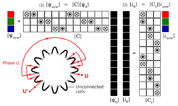
 Fig. 1 Connection matrices for current (right) and flux-linkage or voltage (left)
Last month the letter K failed to provide a ready supply of suitable electrical engineering topics for the Diary, so we borrowed the German term Kennlinie. But if we widen the search to include the names of distinguished engineers we will find several beginning with K. We aren’t in the business of giving prizes or even trying to rank them, but one who deserves special recognition is surely Gabriel Kron (1901–1968). Kron’s work was quite mathematical and mainly concerned with the analysis of electrical networks with complicated interconnections. It was prescient in anticipating the age of digital simulation and the use of matrices, even though much of it was published in the 1930s.
Kron’s work is perhaps best known in the field of power-system analysis, but it seems to be worthwhile to reflect on one aspect of his work that is especially relevant to electric machines: that is, the idea of the connection matrix. In electric machines the obvious example of an ‘electrical network with complicated interconnections’ is the winding. A winding can be defined as a set of interconnected coils, and the Blue Book has a 3-phase example with 12 coils in 12 slots with 10 poles. This example is depicted graphically in Fig. 1, which has four parts: the two matrix equations (1) and (2), the set of unconnected coils coloured black, and the interconnectors for phase U coloured red.
The starting-point is the set of unconnected coils, which Kron calls the ‘primitive’ set. At the right-hand side of eqn. (1) is a column vector [ψ0] of the flux-linkages of the 12 individual coils, which can be seen as an array of dimension 12 × 1 (12 rows and 1 column). Normally the elements of this column vector will be the numerical values of the respective flux-linkages, but in Fig. 1 they are shown by a black colour-fill in order to develop a geometric image of the connection matrix theory. The numerical values per se are not important in this theory, so the black colour-fill tells us everything we need to know about them, which is essentially nothing — just the fact that they are stored in the column vector [ψ0].
On the left-hand side of eqn. (1) is a 3 × 1 array or column vector of the flux-linkages of the three phases U, V and W. Again the numerical values are not important but the colour-fill is now used to distinguish the three phases with colours red, green and blue. Equation (1) defines and expresses the relationship between the flux-linkages of the 12 coils and the flux-linkages of the three phases.
In the simplest case when the individual coils belonging to any phase are all in series, the phase flux-linkage is simply the sum of the flux-linkages of those individual coils. A similar summation is applied for each phase in turn, resulting in eqn. (1). The coil flux-linkages have to be added with the correct polarity, as defined by the interconnectors. The polarity can be positive or negative, so there are two symbols for the connection coefficients, one representing a ‘go’ polarity and the other one a ‘return’ polarity. The matrix is the [3 × 12] connection matrix [C], while [ψuvw] is the 3 × 1 column vector of phase flux-linkages and [ψ0] is the 12 × 1 column vector of individual coil flux-linkages. Each element of the connection matrix has the value of 1 or −1, for a coil that is connected; or 0 for a coil that is not connected. (Blue Book, p. 57).
We can test the conformity of these arrays for multiplication by noting the sequence of dimensions in the form of an equality: [3 × 1] = [3 × 12] × [12 × 1].
We should note that the same form of eqn. (1) also applies to the voltages, since the voltages in a circuit can be added by Kirchhoff’s first law. The addition of flux-linkages is valid even when the magnetic circuit is non-linear, because it amounts to a partition of the line-integral of vector potential around the complete circuit, which is independent of the state of saturation of the materials.
Now we come to an intriguing property of circuits, which can be seen by reference to eqn. (2) on the right-hand side of Fig. 1. This equation expresses the relationship between the currents [i0] in the individual coils (the 12 × 1 column vector with black colour-fill) and the currents [iuvw] in the three phases (the 3 × 1 column-vector with red/green/blue colour-fill). The matrix relating these vectors is the transpose of the connection matrix [Ct], and it appears in eqn. (2) with the same elements 1 or −1 which are denoted in Fig. 1 by the ‘go’ and ‘return’ polarity markers for the interconnectors.
What is remarkable is that once the voltages or flux-linkages have been related by the connection matrix [C] as in eqn. (1), the relationship between the currents follows immediately as in the transpose eqn. (2).
Note that the connection matrix is not square. This means that it cannot be inverted. To see the physical significance of this, imagine that the flux-linkages [ψuvw] of the three phases are known. It is impossible to solve eqn. (1) uniquely to determine [ψ0], the flux-linkages of all the individual coils. In practice this is not a limitation, because the connection matrix is used in such a way that inversion is never required.
We can say that the connection matrix defines the interconnectors, not only in terms of their physical connections but also in terms of the mathematical constraints they impose on the currents, flux-linkages and voltages. So the connection matrix can be used equally in the winding shop or in setting up an electrical analysis of the properties of the winding.
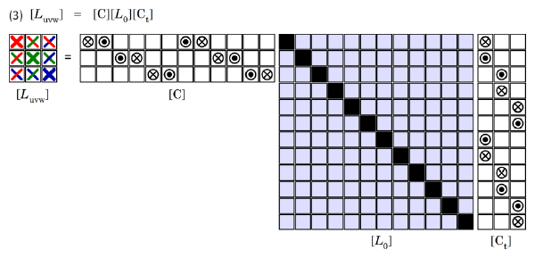
A further application of the use of the connection matrix is shown in Fig. 2, where the phase inductance matrix [Luvw] at the terminals is assembled from the primitive inductance matrix [L0] by means of eqn. (3). This entails a pre-multiplication by [C] and a post-multiplication by [Ct]. To check the conformity of the respective matrices for multiplication, we can write [3 × 3] = [3 × 12] × [12 × 12] × [12 × 3]. The colouring of the inductance symbols in [Luvw] reflects the nature of the self- and mutual inductances in terms of the coupling between phases.
 Fig. 2 Connection matrices used to form the phase-inductance matrix
The primitive inductance matrix is in general full, because every coil has a self-inductance (marked by the black elements on the diagonal), and a mutual inductance with every other coil. The mutual inductances (coloured light blue) appear in the off-diagonal elements. In a magnetically linear machine we expect the mutual inductances to be reciprocal, making [L0] symmetric; but magnetic non-linearity disturbs this symmetry, sometimes to such an extent that it becomes questionable whether inductance is even useful. In such cases there is an argument to work exclusively with currents and flux-linkages (and voltages), and avoid inductance altogether.
In electric machine analysis, inductance is actually unnecessary. It is not needed in the calculation of voltage, flux-linkage, current, or torque. These quantities can be computed perfectly well by the finite-element method together with Faraday’s law, without using inductance. Without inductance, in the example we have 12 primitive currents, 12 voltages and 12 flux-linkages, and the connection matrix has 12 non-zero elements. When the connection matrices are applied, we have 3 currents, 3 voltages and 3 flux-linkages, and the relationships between them will be calculated by the finite-element method. With inductance, we have also to deal with an inductance matrix with 144 elements, which reduces to an inductance matrix with 9 elements. Because of saturation, neither of these inductance matrices is in general symmetric, and that is a source of confusion and uncertainty that is completely avoided when the analysis is formulated without inductance purely in terms of currents and flux-linkages.
The connection matrix can be used (with variations) for any interconnected network, but this simple example is enough to show the dramatic simplification of the terminal quantities (current, flux-linkage, voltage, inductance, and resistance as well). It is not simply a question of collapsing a large inductance matrix into a small one. It is also a means of organizing the separate currents, flux-linkages and voltages in a systematic way — an algorithmic way — which is suitable for circuit analysis. Kron [1939] gave several examples much more complex than the one we have used here.
The connection matrix is one of the jewels in the far-sighted work of Gabriel Kron. He went much further in circuit analysis, developing the theory of tensors, the subject of a complete book by L.V. Bewley in 1961. In my case I had a copy of Kron [1959] as a student in the 1960s, but I found it difficult to digest: the writing is compressed and not didactic, and the subject of tensor analysis seemed too abstract — a step too far for a mere engineering undergraduate. In half a century, progressing from a state of zero knowledge to a state of a small amount of knowledge, I’m afraid I have consolidated this view, for two reasons. First, tensor analysis relies on simplifying assumptions (listed explicitly by Bewley) that severely limit its application to real-life problems in electric machine analysis and design. (Neglect of saturation is just one of these assumptions). Secondly, the analysts of Kron’s and Bewley’s era did not have the modern digital computers (nor the software) that we have today. So we see in their works (and in contemporary works in other disciplines) a heroic search for general methods and results that would cover the widest possible range of circumstances and conditions. The digital computer has completely changed our approach: instead of the process of analysis – formula – substitution we now go directly to simulation, starting with the fundamental differential equations, bypassing classical analysis, and producing numerical results directly. We do this for all the disciplines of physics, and we are not limited by the complexity of circuit interconnections or magnetic nonlinearity or any of the other natural complications that Bewley had to neglect.
Yet we have gained enormously from the vision of Gabriel Kron in the simple concept of the connection matrix (and many other precepts in his rich legacy). The assembly of coils into complete windings is an obvious and necessary step not only in the factory, but also as a precursor to the entire theory of windings in all kinds of electric machines.
The application of the connection matrix in eqns. (1–3) can be classified as a transformation or mapping. Speaking in terms of the inductance matrix, further simplications are commonplace and one of the most useful in AC machines is the dq-axis transformation (Park’s transform), in which the phase inductance matrix [Luvw] is premultiplied and post-multiplied by the transform matrix and its transpose. With a properly chosen transform matrix and sine-distributed windings this results in the diagonalisation of the inductance matrix, which means that while we still have three circuits (d, q and 0) they are independent of one another — in other words mutual inductance terms disappear (they are in fact absorbed into the so-called synchronous inductances). In this case, as is well-known, the zero-sequence circuit is null with a 3-wire connection, so the practical result is a reduction from 3 circuits to only 2. For non-salient-pole machines the d– and q-axis circuits are symmetric and many problems can be solved with only one of them.
Kron’s connection matrix makes all of these facilities available directly and algorithmically, starting from an unconnected set of coils (the primitive set) and a simple definition of the interconnectors.
Bibliography —
Kron G., Tensor Analysis of Networks, Wiley, New York, 1939.
—, Tensors for Circuits, Dover Publications Inc., New York, 1959.
Bewley L.V., Tensor Analysis of Electric Circuits and Machines, Ronald Press, N.Y., 1961.
Blue Book : Hendershot J.R and Miller T.J.E., Design Studies in Electric Machines, MotorDesignBooks.com, 2022. See Column 52, December 2022.


