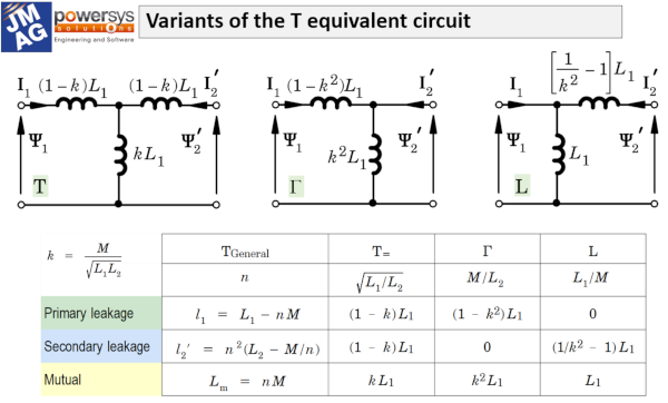
 Fig. 1 Mutual inductance ‘buried’ in several conventional variants of the equivalent circuit (from Video 39)
Mutual inductance M is one of the most common concepts in electromagnetic engineering. Indeed we can argue that it is also one of the most fundamental concepts. In any electromagnetic device having more than one electric circuit, it defines the interaction between those circuits that arises from the common magnetic field. Although field calculations are necessary to calculate it, the parameter M is subsequently used in circuit calculations without further reference to the field calculations or even to any aspect of the magnetic field from which it arose.
In the domain of circuit calculations it is common to find equivalent circuits whose relationship to the actual circuit (the winding diagram) may not be obvious. A familiar example is the equivalent circuit of a single-phase transformer, which is practically identical to the positive-sequence equivalent circuit of the induction motor. Both these devices obviously have two or more actual circuits, and in the motor at least one of these circuits is rotating while at least one is stationary. Naturally we expect to find mutual inductance in these circuits, and in the case of the induction motor we might expect the mutual inductance between stator and rotor circuits to vary as the rotor rotates.
The equivalent circuits most often used for both these devices are typically of the form of the T diagram in Fig. 1, although the Γ and L variants are also used in space-vector control theory and in test and measurement. The disturbing thing about these diagrams is that if we look for the mutual inductance M we cannot immediately see it.
In elementary textbooks the two electric circuits are often described in terms of their respective self-inductances L1 and L2 and the mutual inductance M, and these parameters can in fact be found in the table in Fig. 1 But in engineering treatments (especially those concerned with design and control) the equivalent circuits are more common; the textbooks often rush to establish them on purely physical arguments with scant attention to the more basic model of two coupled circuits with L1, L2 and M. There needs to be a rigorous theory that shows the equivalence of the various forms. Such a theoretical account is attempted in Videos 36-39, and this Diary is a practical commentary written a little distance from the mathematical details.
Many years ago a young (and very perceptive) colleague once commented that ‘inductance is all mutual’, [1]. He was engaged in calculating the inductance of superconducting field coils using the line-integral of magnetic vector-potential along the filamentary centre-lines of the conductors. Nowadays this method (which we often associate with Stokes’ theorem and Gauss’ law) is the natural way to calculate inductance using the finite-element method. In the discretized mathematics of digital numerical analysis, the integral is a sum of contributions evaluated at the site of every element j of a circuit due to the current in every other element k, k = 1 .. N where N is the number of elements into which the circuit has been divided. The difference between self-inductance and mutual inductance is then purely a matter of where the current is flowing — in the same circuit or in a different circuit. We can see how the parameters L1, L2 and M arise naturally in this approach.
But when an engineer tests an induction motor or a transformer, the standard tests are to measure the open-circuit voltage and the short-circuit current, and the instruments include voltmeters, ammeters, wattmeters, (and sometimes power analyzers which fulfil the functions of all the separate meters). It is very rare to find an inductance bridge involved in these tests, and still rarer to find a flux-meter (which in the author’s opinion is the correct instrument for the measurement of inductance of electromagnetic power devices [2]).
From the standard tests the standard equivalent circuits are deduced heuristically or phenomenologically — meaning that they have been found to fit the behaviour as tested, and that is why the parameters L1, L2 and M seem to be left out, even though they appear to be essential in the pure elementary physics theory. Videos 36-39 attempt to resolve this ‘dichotomy’ between the disjointed theories of simple coupled circuits.
The coupling coefficient k (Fig. 1) expresses the relative tightness or closeness of magnetic field-sharing between coupled circuits, and in transformers and induction motors its value is quite close to 1. This explains why L1, L2 and M are relatively close in value (when referred to the same number of turns). The performance of both transformers and induction motors depends rather critically on the leakage inductance which can be generically expressed in terms of (1 – k) and the short-circuit inductance which can be generically expressed in terms of (1 – k2). When k is close to 1 it is difficult to measure it with sufficient accuracy to give reliable values for (1 – k) and (1 – k2), and that is a practical reason why inductance bridges are not appropriate in the standard tests for transformers and induction motors, no matter how accurate they may claim to be. (It is also easy to get spurious readings from such instruments especially if they use high frequency or small signals).
We can infer from these warning comments about the use of inductance bridges that the finite-element method has the same vulnerabilities as those instruments. Whereas the finite-element method naturally evaluates L1, L2 and M, it is not capable of calculating leakage inductance or short-circuit inductance directly.*
We can thus see a scenario in which the designers and test engineers speak one language (the language of standard tests and equivalent circuits), while the finite-element engineers speak another (the language of magnetic vector potential and inductance). If the test engineers do not practise the finite-element method, and the finite-element engineers never visit the test laboratory, how can they possibly work together?
My personal answer to that question is that, taking the industry as a whole, they do work together and they cooperate extremely effectively : we only have to look at the products of advanced engineering to see that this is so. But the rigorous equivalence of the equivalent-circuit models and the apparently simple physics of L1, L2 and M is not easy to find in the familiar textbooks, and that is the rationale behind Videos 36-39.
Although this story might be taken to ‘marginalise’ the finite-element method on the grounds that it is out of joint with standard test methods and equivalent circuits, the irony is that the finite-element method is the ‘saviour’ that allow us to deal with some of the intractable weaknesses in the standard test methods and equivalent circuits : for example, saturation, core loss variation, and eddy-currents. It can be argued (and sometimes is argued) that if you have a simulation capability that is so comprehensive as to model every aspect of a product accurately under all conditions, the equivalent circuits and even the standard tests become unnecessary.
I hope this won’t happen in my lifetime, because although I recognize and value the revolutionary effects of numerical analysis, like everyone else, I still need the equivalent circuits to express the basic operation and performance of my transformers and motors. I am not alone in this. Steinmetz himself had the same view when he devised these circuits! Control engineers rely on equivalent circuits and use them with sophistication at least equal to what see in field analysis. The same is true of power-system engineers in connection with vast interconnected circuits working at many different voltages.
In the cooperative environment of all these specialists, much of the communication between disciplines is in terms of jargon — such as ‘inductance’ itself. We hear the term all the time, and of course we ‘know’ what it means; but when we go into the details, the dependencies, the complications, the variations and uncertainties, we find quite a morass. Videos 36-39 attempt a rigorous explanation of one tiny patch of this common ground.
Maybe we could redefine ‘mutual inductance’ as jargon for the concept that allows mutual coupling between engineers who have very different perspectives on their electromagnetic calculations and measurements. All inductance is mutual.
References :
[1] Richard Langman, 1971. Private communication.[2] Green Book Design of Brushless Permanent-Magnet Machines, §13.10.


