[No. 81] Flummoxed by Flux-Waves?1
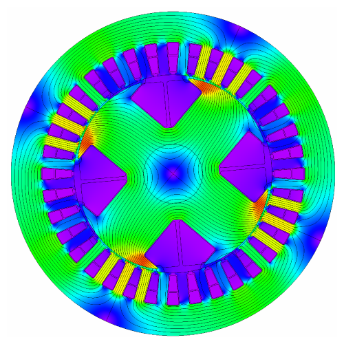
Fig. 1 Flux-plot in a wound-field synchronous machine under load
Electric machine engineers often speak of the flux wave in the air-gap of an electric machine, yet when we look at a flux-plot such as Fig. 1 we cannot see it. Fig. 2, on the other hand, is an example of a flux wave calculated by JMAG for an induction motor at no-load with three different amplitudes of the magnetizing current. Each solid graph is obtained by sampling the radial component of flux-density in the middle of the air-gap over an angle of two pole-pitches. The classical theory of AC machines is based on the fundamental space-harmonic component of such waves — that is, the space-harmonic defined by the working pole-number. The fundamental components are shown in dashed lines in Fig. 2. They are obtained by Fourier series analysis of the solid graphs (not the FFT).
It is clear in Fig. 2 that there are many higher-order harmonics as well as lower-order harmonics of orders such as 3,5,7, etc.; and it is even possible that there may be some ‘subharmonics’ with fractional electrical orders less than 1 — we cannot tell simply by looking at the flux-waves, but only from the Fourier series analysis. What is remarkable is that reliable values for the torque and the phasor values of the terminal voltages can be estimated from the fundamental component at any particular load-point using classical theory, especially when the requisite flux-waves are calculated using the finite-element method. The harmonic components are associated only with harmonic leakage inductance, torque pulsations, and parasitic losses, and not with the main mechanism of torque-production. These aspects are so complex that the finite-element method is essential to get accurate results in design calculations.
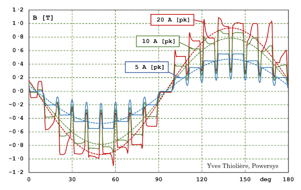
Fig. 2 No-load flux-density distributions in a 3-phase induction motor
The mindset of the classical electric machine engineer is to focus on the fundamental of the flux-wave, trying not to think of the horrid harmonics that we see in Fig. 2. If we could go back to a design office of 50 years ago, we might find that most engineers had no idea how messy Fig. 2 could be, because they had no means of calculating it precisely.
At that time it was widely held that the ideal flux waves of AC machines should be sinusoidal, and that the important quantity was the fundamental flux. Equally for DC machines it was well understood that the total flux/pole was the most important quantity, and it would be rare to find any space-harmonic analysis of the air-gap flux in a DC machine. (The open-circuit flux-wave in a DC machine would normally be rectangular, not sinusoidal.) These ‘canonical’ waveforms (rectangular for DC, sinusoidal for AC) were rarely questioned as to their suitability for their respective purposes.
From about that same time, roughly 50 years ago, coinciding with the introduction of the brushless DC motor, questions began to be asked about the ideal form of the flux-wave. 2 The brushless DC motor had a trapezoidal or nearly-rectangular open-circuit flux wave (like that of the DC commutator motor), and it had ‘square-wave’ currents of rectangular wave-shape, commutated in 60° ‘blocks’ or pulses, [1]. Which was better, squarewave or sinewave current? Trapezoidal flat-topped EMF or sinusoidal EMF?
We know now that ‘sinewave’ emerged as the front-runner — certainly in ‘high-performance’ machines; and it retains that pre-eminence today, even though squarewave brushless DC machines are still widely used in low-cost applications.
But was there (and is there) an even better alternative? Could some of the harmonics in the air-gap flux-wave be used to increase the torque beyond what was possible with the fundamental alone? Was the sinewave indeed the optimal waveform for the current?
These questions led to the development of a wide range of alternative ideas and complete drive systems, in which we have seen much innovation not only in the machines but also in their controls (inverters). All these have in common the attempt to improve the AC machine by exploiting the space-harmonics in the flux-wave. Some have been commercially successful; and although they are not numerous relative to the standard 3-phase AC system, they have proved themselves valuable for special applications.
We can trace the development history with reference to a few key terms such as ‘asymmetric six-phase and nine-phase induction motors’, ‘third-harmonic current injection’, ‘multi-phase drive systems’ (including 5-phase and 7-phase), and associated development avenues such as ‘bi-harmonic machines’ and ‘permanent-magnet profiling’. The scope of these subjects is now so wide as to make it quite hard to disentangle all the different developments and relate them to the fundamental principles of AC machines. In the remainder of this Diary I would like to draw attention to what seem to me to be some seminal papers, and to outline a few of the basic principles (as far as I understand them).
Discussion of rotating MMF waves
A single phase winding produces a stationary MMF wave with space-harmonic components of order m obtained by Fourier series analysis of the winding function or ampere-conductor distribution in mechanical degrees or radians. 3
When this winding is excited with current, all the space-harmonic components are modulated with the same time-waveform as the current waveform. If the current waveform is analysed into time-harmonic components of order n, every mth space-harmonic component of the MMF distribution is modulated by every nth time-harmonic of the current. We therefore have a set of mn space-harmonic components to work with, and they are all pulsating or alternating in time, but stationary (i.e., not rotating).
Let us pick one of these stationary space-harmonic MMF waves with mechanical space-harmonic order m and time-harmonic order n; and suppose that we want to create a rotating MMF wave with the same number of harmonic pole-pairs (m). From the elementary theory of 2-phase windings we should be able to do this by adding a second phase identical to the first, but whose axis is displaced 90/m mechanical degrees from that of the first phase, and supplied by an nth time-harmonic current 90° out of phase with the nth time-harmonic current in the first phase.
What this describes is an ideal 2-phase machine with m harmonic pole-pairs, excited with balanced 2-phase AC of frequency nƒ [Hz], where ƒ is an arbitrary ‘fundamental’ frequency or reference frequency. The harmonic MMF rotates at the corresponding synchronous speed nƒ/m rev/sec.
We could have three phases instead of two. In that case the axes of the three phases should be uniformly spaced at 120/m mechanical degrees. The synchronous speed for the selected mth space-harmonic and nth time-harmonic would be the same, nƒ/m rev/sec. It is fixed by the number of harmonic pole-pairs m and the time-frequency nƒ, and is independent of the number of phases. The number of phases will be decided according to other criteria such as the current and voltage ratings of wires and circuits and control devices (including semiconductor devices).
We know that in practice it is impossible to construct a pure AC machine with only one space-harmonic MMF, because of the distribution of a finite number of coil-sides in a finite number of slots. It is possible to obtain a nearly sinusoidal current time-waveform; but in general in a practical machine there are many space-harmonic components of MMF, and they are all excited by all the time-harmonic components of the current waveform. The best that can be done — and this is the normal practice — is to reduce both the space-harmonics and the time-harmonics to tolerable levels consistent with the application requirements. 4
There are several interesting cases where engineers have sought design improvements — particularly in relation to the torque or the torque ripple — by adding back some of the harmonic effects, apparently going against the grain of long experience in which all harmonic effects (apart from those of the working harmonic) were regarded as parasitic and undesirable, and which from early times design engineers have striven to minimize.
Three notable principles are well documented in the literature. They are not so clear-cut as to be absolutely definitive of any particular ‘class’ of system: there is quite a degree of overlap between them, and many complicating factors and side-issues. But they do provide a framework, so let’s work through them. We can denote these ‘notable principles’ as
| P1 | production of torque by the interaction of like-order space and time-harmonics combining to rotate forwards at synchronous speed; |
| P2 | enhancement of the fundamental flux/pole by third-harmonic injection; |
| P3 | the squarewave brushless DC motor which (like the DC commutator motor) appears to use all the space- and time-harmonics. |
But let’s start with the dual three-phase motor, which provides a historical basis for multi-phase drives and their attributes, as well as the platform for the beneficial introduction of third-harmonic effects.
The dual three-phase motor (also known as ‘asymmetric six-phase’) has two sets of three-phase windings displaced by 30°elec. (not 60° as they would be in a symmetrical 6-phase layout); (see [1], chapter 10). This arrangement was developed in the early stages of AC drive technology to facilitate large motor drives with 6-step current-source and voltage-source inverters at a time when semiconductor device ratings were a limiting factor, including fault-tolerant properties; (see Jahns, [4] and Abbas et al [5]). Success with this scheme brought out many other advantages that were progressively attributed to ‘multi-phase’ systems more generally, and more complex systems were developed with nine or more phases, even before the introduction of PWM current-regulated inverters capable of controlling the harmonic content of the current waveform.
A further inventive step was to inject a third-harmonic component of current into each of the two sets of three-phase windings, as described by Lyra and Lipo in 2002 [7] in connection with induction motors. Reference [7] employs both principles P1 and P2, and evaluates their relative worth. Lyra and Lipo define two sets of zero-sequence third-harmonic currents that are orthogonal in phase at the third-harmonic frequency, while the 30° displacement between the two sets of windings is equivalent to 90° in respect of the third space-harmonic. These are the conditions that enable the injected third-harmonic to produce constant torque, provided also that the third-harmonic winding factors are not zero. The earlier reference [6] provides a comprehensive analysis of the benefits of interaction of higher-order harmonics on the MMF and the torque production (including torque ripple). The intention appears to have been to evaluate which of the systems feasible at the time gave the most favourable harmonic content, rather than to use PWM inverters to force currents with optimized harmonic content. It also evaluates results with different numbers of phases, mostly with current waveforms of rectangular shape (not unlike those of the brushless DC motor, and characteristic of the current-source inverter).
Lyra and Lipo [7] also bring out an indirect but valuable (and perhaps unexpected) effect of the 3rd-harmonic injection, namely an increase in the fundamental space-harmonic component of the air-gap flux density without increasing the peak value; (principle P2). They gave the following equation for the air-gap flux-density distribution with this property:

This equation can be used as a point of reference for the principle of increasing the fundamental air-gap flux-density by third-harmonic modulation, (P2). It arises elsewhere: notably in connection with the injection of third-harmonic modulation in inverter drives (mainly to increase the speed range in the over-modulation range); and also in connection with the shaping of permanent-magnet rotors or their magnetization patterns (see, for example, Lin et al [8] and Wang et al [9]).
While the torque can be increased by means of the increased fundamental air-gap flux-density (P2), it can also be increased, as we have seen, by interaction between the third space-harmonic component of the winding MMF distribution and the third time-harmonic in the current waveform, (P1). The interaction of like-order harmonics is what makes the third-harmonic components rotate at the same speed as the fundamental or working harmonic. Although this was recognized in the papers by Lipo et al [6], and implemented in a dual three-phase motor in [7], the principle was pursued and developed by Parsa and Toliyat [10] specifically in a 5-phase surface-magnet motor, not relying on any enhancement of the fundamental component of air-gap flux-density. We can identify this as a second main example of principle P1 in connection with the exploitation of harmonic effects. Ref. [10] describes the design of a special 5-phase motor and discusses the choice of the numbers of slots and poles, which of course fall outside the combinations found in 3-phase machines.
Most of the later authors mentioned above described field-oriented PWM inverters in which the first and at least one higher-order harmonic in the current waveform were combined and controlled in dq-axes. They all used finite-element analysis to verify and deepen the basic theoretical models, and circuit-simulation software to develop their controls. The finite-element analysis has also proved itself important in the estimation of parasitic losses which are more complex than in the simple standard polyphase machines.
The technology of multi-phase motor drives has continued to develop, with many interesting innovations and variations in both permanent-magnet and induction motors (and others); but it is hoped that these early works will stand out as helpful references in any study of these systems.
Although there may be only a tenuous basis for including it here, the third principle (P3) in the exploitation of harmonic effects is that of the square-wave brushless DC motor [1], in which square-wave currents are block-commutated in windings that are more nearly concentrated than sine-wound, and in which the air-gap flux-distribution is more nearly a trapezoid than a sinewave. These motors, which date from the mid-1970s, could even claim to be the original users of the harmonic effects that the designers of AC machines strove to eliminate. But this would be ‘a bit rich’. The brushless DC motor derives from the idea of block-commutation (as in a DC motor with very few commutator segments), and very little harmonic analysis has ever been used in its design; nor was it ever needed. 5 However, it still benefits from the same finite-element analysis and circuit-simulation software as all the AC motors: in fact, as far as those software tools are concerned, there is very little difference in the way they are used; what is different is the rich classical theory of harmonic effects that is peculiar to the AC machines.
Final thought — Looking back at Fig. 2, it seems astonishing that anything efficient or smooth or controllable could come out of such a messy collection of harmonics, even in a machine that uses only the fundamental working harmonic. It is even more remarkable that improvements in torque density and torque ripple can be distilled from this stew of harmonics in multi-phase drives with optimized harmonic content in the MMF, current, and rotor profile. The technology of multi-phase drives is a perfect example of the effective combination of classical theory with finite-element analysis, circuit simulation and field-oriented control theory, as we can clearly see from recent publications such as [11‐15].
Videos 62‐64 present a more detailed review of the principles and advantages of multi-phase machines, including the mathematics of the space- and time-harmonics and details of winding configurations and theoretical rules that can be traced back to 1916.
Notes
1 ‘Flummoxed’ = ‘confused’ or ‘perplexed’. Note that this Engineer’s Diary is based entirely on the works listed in the References, and contains no proprietary information. The same is true of Videos 62‐64.
2 Also at about the same time, the switched reluctance motor emerged as a serious contender in adjustable-speed drives, while stepper motors and other specialty motors were vigorously developed; many of these did not follow conventional principles and therefore they did not use the ‘canonical’ DC or AC flux-waves. They also fell outside the scope of the so-called ‘unified’ or ‘general’ theory of electric machines, which reached its most prominent level in the 1960s, [3]. Heavy reliance on ‘canonical’ waveforms made it difficult for the unified theory to keep up with machine developments that ventured beyond the canons. In a sense the finite-element method (and computer simulation more generally) came to the rescue because it has none of the limitations imposed by classical theory. Even Park’s transform has to be used with care, since it relies on ‘canonical’ waveform concepts in much the same way as the unified theory; but it is redeemed by reliable parameter calculation methods based on the finite-element method.
3 The MMF (magnetomotive force) waveform of a winding is the integral of its ampere-conductor distribution around the air-gap with respect to angle. Divided by the current, the latter is the ‘winding function’. See [2].
4 Note that up to here we have been discussing only the MMF wave and not the terminal voltage or the torque. In both of these there are further considerations about time-harmonics, which depend on the nature of the rotor.
5 Nonetheless, harmonic analysis of the brushless DC motor did give rise to the idea that with squarewave flux distribution maybe the fundamental would be increased by a factor of 4/π, giving 27% more mean torque. This would require a squarewave MMF distribution rotating bodily without distortion at synchronous speed — easier said than done.