Motor Design Course
In the September 2013 issue of this newsletter,the first of these ongoing columns, I gave an explanation about the background to starting a course on motor design. In this issue and the second column, I'll finally get around to explaining what's involved in designing motors. The theme of this column will be to provide a starting point for concept design. Although it may seem a little boastful, what I'll do is go over some of the results that we have obtained through our studies and, hopefully, these will be of use to your work.
Motor Concept Design
When starting out on a motor design, the first thing that must be done is to clearly establish the precise reason for why you are designing a motor. There is always an objective for starting a development. Clarifying this objective enables defining the directions that are to follow.
Whether designing a variation from an existing product base or working on improvements of defects, existing products are always the place to start. Even with a completely new design, it's normal to start working from existing products that have similar performance or size to the desired product. Existing products derived from a variety of examinations of results and been evaluated as competitive, so they have reliability and results, even if aspects about them remain a matter of concern. I'm not suggesting you place blind faith in existing products, but want you to know that they are important when it comes to moving ahead on new designs because that involves reassessing existing designs.
I'll put aside the picky stuff from now on and move onto some details. Fig. 1 is a simple summary of the flow of a motor's concept design.
 Fig. 1 Motor Design Flow
Start from your requirements, decide on rough characteristics then check performance matters based on experience values, including output, torque and thermal suitability. Finally, decide on items such as the model geometry and coil diameter of the magnetic circuit and summarize all of these as the initial design proposal. This initial design proposal will serve as the springboard toward a more detailed design.
First Decide on Size
Items, and I'm not talking about just motors here, have a proper size. From IT equipment or smartphones used in the palm of the hand through to supercomputers that occupy entire buildings, items have a size depending on their performance and capabilities. Of course, there are precious works of art whose value cannot be calculated, but the size of a device is usually determined while based on the role it has to play. Putting it another way, the density of a particular job will be decided according to the specific unit weight. With motors, the smaller the motor, the lower its output and the bigger a motor the greater its output can be.
Items weighing a lot are also large and their heat capacity and heat release area are also enlarged, enabling significant output. This is not something that needs to be re-thought, but you do need to be aware of it as you'd be surprised by how many times people don't get it right.
Looking back over existing motors, you'll learn there's a proper value for rough weight output density. I'd aim for about 0.3 to 1.0 kW/kg. If setting the output density at a low figure, you're in a position to consider you have given yourself some breathing space. For motors used continuously, like those powering factory lines running night and day or used to drive bullet trains, you must consider that maximum rating is equal to continuous rating. Phrasing it another way, you can expect to create characteristics of endurance, like a marathon runner who is always running continuously. Alternatively, raising the output density setting will eat into your breathing space. You need large output in a short time like a commuter train accelerating, but once you're cruising, you can set a higher output ratio. Continuing with the runner analogy, in this case the characteristics are more of a short-distance runner than a marathoner.
For this example, we'll use the following:
Output: 1kW, 2.5Nm/4000rpm(A)
Input: 200V/7A
to design a motor. Applying an output density of 1kW to a motor gives you weight in the 1kg to 3.3kg range. As stated earlier, 1kg is like a high performance sprinter and 3.3kg is more like a marathon runner with endurance.
Specify the output density while allowing for the size of the output permitted by requirements and the rating time necessary for this. But, you should note that it's not worth too much worry over this at this stage, so I decided by just throwing in a number. Being typically Japanese, I went for the middle of the road and chose a design for a weight of 2kg.
If the iron of the specific gravity of the motor materials is 7.8g/cc, content of 256cc will be necessary to make 2kg. There are multiple combinations of the outer diameter and outer radius to make 256cc (See Table 1).
Table 1 Combination of the Outer Diameter and Outer Radius
 Fig. 2 Same-volume Cylinders of φ40/L200 and φ80/L50
Even though they have an identical volume, they have completely different feelings with one being long and thin and the other short and fat. Nonetheless, the weight remains the same, so it's difficult to decide on one or the other.
Select from this combination in accordance with requirements. Decisive factors will be such things as ease of incorporation into equipment, ease of positioning and ease of production. Here we'll look at the comparatively middle of the road φ80mm ~ L 51mm (Fig. 2)
Next, we'll decide on the rotor diameter. Setting the rotor diameter at 50% of the stator diameter gives good balance if you're dealing with the inner rotor. The larger the diameter, the greater the tendency for increased percentages. If it's the outer rotor, most gather somewhere from 70% to 90%. We will use a standard inner rotor and decide on a rotor diameter of φ40mm, which iis 50% of the stator diameter.
Next, we'll decide on the number of poles. Use the size of the magnet or number of slots as a guide for deciding on the number of poles. For each pole, an extreme-sized magnet, either small or large, will adversely affect performance and make it more difficult to create the magnet. A design with a magnet width from 10mm to 100mm works as a guide. Here, the rotor diameter has been decided on as being φ40, so the rotor circumference is 125.7mm. If there are four poles, the circumference is 31.4mm, so this is perfect as the magnet will be neither too small nor too large.
We have decided on four poles, so the number of slots should be six with a concentrated winding and either 12 or 24 with a distributed winding. Our design is comparatively voluminous, so we'll use distributed winding. Concentrated winding enables lowering the height of coil ends, but this is best utilized with small, thin motors of small volume. Each turn of the coil is short, so that also reduces copper loss. Distributed winding raises the coil end height, but has the benefit of increasing the number of slots per pole, making it easier to create a weak field control effect and reducing iron loss and magnet eddy current loss (Fig. 3).
 Fig. 3 Concentrated Winding (above) and Distributed Winding (below)
The slot pitch in concentrated winding is 1, so it controls the height of the coil end to prevent it from overlapping with the coil in another phase. As there are at least three slot pitches in distributed winding, the coil end becomes higher and motor length
With distributed winding, the slot pitch (arc) is 5.2mm with 24 slots of 10.5mm with 12 slots. If the slot pitch falls below 10mm difficulties arise from a production capability point of view, so we'll examine a case here using 12 slots.
Deciding on the number of poles is a comparatively major judgment, but it affects only the internal area of the motor and has only limited impact on the exterior or output, thus changes can be made at the stage when you're moving forward on detailed design. Changes in concentrated or distributed winding, or in the number of slots, can be undertaken during detailed designing, so don't really need to be given a great deal of thought at this stage.
Check torque density (thrust density)
In the previous section I mentioned that required output plays a large part in determining size. At that time, you'll also find aspects important for deciding whether output should peak for a short time or endure for a long time. However, you should note there are times when it's best not to limit operation to a short time. To give an example in terms of humans, remember even Olympic athletes are incapable of sprinting 50km or lifting over 400kg. Applying the same logic to motors should limit the torque to what is capable of being drawn out from the weight. As I'm sure you're all aware, magnetic circuits are subject to a phenomena known as magnetic saturation. This has a significant association with torque (thrust force), with a limit to the force that can be output per unit of volume and attaining magnetic saturation when it achieves that value.
As torque depends in some aspects on the model geometry, I recommend evaluating through the more common thrust density. Essentially, this means there's a standard value for the force for each gap face. Areas where the motor generates torque are air gaps between the rotor and stator. Consequently, this area and force will influence the size of the torque. The gap area is determined by the stack length and rotor radius (Fig. 4).
 Fig. 4 Air Gap Regions in a Motor
Multiplying the targeted torque by the rotor radius will obtain the radial directional thrust force that should be generated from the gap area. By the time thrust force has developed, the contribution of the rotor radius ends and there is an exchange of force with each unit area. Imagining this situation from a mechanical engineering viewpoint, the stator and rotor moving into the air gap creates a shape like those generated through torsional shearing stress.
The rotor radius is φ 40mm and stack length 51mm, so the gap area surface is 6409mm^2. As the targeted torque is specified as 2.5N/m, there is a need to divide the rotor radius 20mm by the force 125N. The 125N/m will bear the 6409mm^2 face and the thrust force density per unit face will be 0.0195 N/mm^2.
The standard value of the thrust force density is about 0.02N/m to 0.06N/m. This shows us that our figure of 0.0195 leaves us with margin of space. Having the margin for this value means there is margin with the torque, which means it's possible to reduce the stack length or cut the rotor radius.
Our examination focused on the torque density, but at this stage there's also a necessity to estimate to a certain extent other factors such as the thermal balance between things like the heat generation amount and radiation generation amount and costs and weight of materials to be used.
Specifying the Magnetic Circuit Geometry
As size largely determines dimensions and we have planned for torque density (thrust force density), we can finally move on to determining the geometry for the motor's magnetic circuits. Key factors are to ensure sufficient surface space for the magnetic flux flowing through the motor, the teeth width in the stator, the yoke thickness and rotor's yoke thickness.
Magnetic flux within the motor circulates including leaked magnetic flux does not boil over or otherwise disappear. Consequently, it's possible to maintain in each area a circuit where magnetic flux can circulate. The gap magnetic flux becomes the basis for estimating this.
Gap magnetic flux density in the vicinity of 0.6T to 1.0T is used in most cases. A guide should be to secure enough space to ensure there are no obstacles to circulation of the magnetic flux. The stator teeth are a silicon steel plate, so you can expect saturated magnetic flux density from 1.6T to 2T. In areas where permeability is high, gap magnetic flux can pass through, so it's possible to narrow that area width.
The stator yoke area aims to flow the magnetic flux that has come from the stator teeth into the adjacent pole, so it's possible to broadly guess the number of teeth.
 Fig. 5 Deciding the Stator Dimensions
The arc of the magnetic pole is 31.4mm. As the magnetic flux emitted from this magnet is drawn from three stator teeth, width of 10.5mm, as 1/3rd of 31.4mm, is needed. Magnetix flux arising from the teeth divides to the left and right of the stator yoke and goes on to the adjacent pole, which shows why we need a thickness of 15.7mm, or half of the 31.4mm.
However, the residual flux density of the magnet is about 1T even in neodymium sintering and allowing for things like magnetic resistance in the gap, it's possible to forecast operating points of about 0.6T to 0.7T. As the stator teeth are silicon steel plates, it's fine to easily expect 1.4T and double that in magnetix flux. Consequently, set the teeth width at half, that is 5mm, and the stator yoke thickness at 8mm (Fig. 5).
Similar thought patterns apply to the rotor yoke (Fig. 6). Magnetic flux flowing from the magnet is washed into the adjacent magnet, showing why we need 15.7mm, or half of the arc's 31.4mm. Saturation magnetic density from 1.6T to 2T such as often used in carbon steel in SPM can also be expected and the stator teeth can similarly be half at 8mm.
 Fig. 6 Deciding Rotor Dimensions
Deciding the Number of Coil Winds
Torque is generated from the build-up of magnetic flux and current, thus the work of deciding on the number of coil winds is equivalent to deciding on the weight of a magnet. Placing magnets with a variety of force enables fewer current ampereturns. On the other hand, even with only a small amount of magnet, increasing the size of the current ampereturns enables obtaining of torque. Current ampereturns are current multiplied by the number of turns. If you have a current of 100A and 1 turn and current of 1A and 100 turns, the strength of the electromagnet face will be the same. The relationship between torque, flux linkage and current is:
Torque (N,m) = Number of Pole Pairs x Flux Linkage (Wb) x Phase Current (A)(A)
Therefore, maximum torque of 2.5N/m with pole pairs 2 and 7A the maximum phase current tells us we need flux linkage of 1.79Wb. As the gap area has been decided in advance, the magnet strength (magnetic flux amount) and number of coil turns needs to be adjusted. Table 2 collates the combination between the number of coil turns and gap magnetic flux to reach 1.79Wb.
Table 2 Combining Coil Turns and Gap Magnetic Flux to make 1.79Wb
Where simply placing rare earth magnets such as happens with SPM, the gap magnetic flux density will be about 0.6T. Increasing the magnets and arranging them in formations such as a V enables increasing the magnetic flux density. Increased magnetic flux density means greater cogging torque, which leads to an increase in iron loss. Air gaps are also subject to armature magnetic flux passing through, so filling these with magnets raises the danger of causing magnetic saturation. Rare earth magnets are also expensive, so there is the additional risk of increasing costs.
Reducing magnets enables lowering of the gap magnetic flux, but we also know this increases the number of coil turns. Increasing the number of coil turns in a coil turning around the same slot face can only be achieved by thinning each coil. Increasing the number of turns will lengthen the coil. For example, doubling the number of turns will have the cross-section face and double the length and resistance and copper loss will increase fourfold. Here we'll use a comparatively large number of magnets and move ahead at 60 turns.
The guide value for the area between the coil cross-section face and current where current passes through is 10A/mm^2. That means we need to ensure at least 0.7mm^2 can be obtained so 7A of current can pass through, with φ1.0 as the guide. The number of turns has been determined as 60, so the necessary slot surface will be 42mm^2, which is 0.7 x 60. However, it's not possible to insert coils so that there are no gaps left in the slot. Using a standard value of 40% to 60% for the lamination factor and then deciding 50% will work shows we need a surface of 84mm^2. As the trapezoidal inside the slot from the stator geometry decided earlier has a top of 5.4mm, base of 11.7mm and height of 11.6mm, we need a surface of 99.18mm^2, which allows us to confirm that we essentially capable of doing 60 turns within the slot (Fig. 7).
 Fig. 7 Slot Area
As the number of coil turns is 60 turns, diameter is φ1.0 (0.7mm^2) and items such as the stator geometry have been decided, it's possible to confirm the coil resistance value. Obtain the initial coil turn length. Axial direction length is 91mm, comprising the outer radius 51mm and one side of the coil end height 40mm. The height of the circumferential arc is the gap radius 40 mm and slot depth 20mm divided by the number of poles to work out at 47.1mm. Thus, the length of 1 turn is:
((51+40)+47.1)×2=276.2(mm)
according to this calculation. This calculation shows that with 60 turns and two poles, the length of each phase will be 33.1mm.
276.2×60×2/1000=33.1(m)
This requires winding an extraordinarily long copper wire. The bobbin area is 0.7mm^2 and copper resistance rate 1.68e-8ohm m, which tells us the resistance value is 0.79ohm per phase.
33.1×(1.68e-8)/(7e-7)=0.79(ohm)
The current passes through at a maximum of 7A, which tells us that copper loss generated at each phase is 39W.
Copper Machines and Iron Machines
There are times when investigating this balance between the magnet magnetic flux and coil turns is referred to as "deciding the load." Magnetic load refers to the gap magnetic density and electrical load is the accumulation of coil turns and current, so the magnetic load significant shows the electrical load for each unit length in the gap area. The motor's output is determined by the accumulation of the electrical and magnetic loads, so deciding these loads is fundamental for the motor's design. Copper machines use copper wire as a magnetomotive force source within motors to increase electrical load and iron motors use magnetics or an iron core with these attributes used to determine the motors characteristics.
Settling the Initial Design Proposal
If you've reached this far, you can now summarize an initial design proposal. Elements obtained are shown in Table 2.
The first hurdle to overcome will be to find out whether this initial design proposal will be able to satisfy all requirements. Check matters such as whether there is sufficient output, or that volume and weight requirements have been met. However, don't forget that this is nothing more than an initial design proposal, so there's no need to think too much about precision as long as you're in the right area. Use this design proposal as a springboard, start examining from the finer areas and gradually improve on the degree of completeness in the design. It's a designer's job to go over and over and over their designs, so good luck and work hard at it.
Don't forget to pay attention when examining results that they are not too far away from requirements. In most cases, there will be an error somewhere within the initial design process, so be prepared to re-check the examination process. Only in cases where it becomes impossible after repeated efforts to overcome an inabilty to meet requirements, talk with the planner to check whether the requirements themselves are the problem. However, there are many cases where the planner is at fault, which means it's highly unlikely that they are going to be particularly conducive to changes. In such cases, throw everything you have at settling the issues at hand. I'm sure the results you come up with will prove to be the best solution.
Table 3 Elements Decided in the Initial Examination
Detailed Examination Next Issue
As mentioned in the previous issue, examinations through to now can all be undertaken easily using the JMAG-Express design tool. It's a tool where geometries can be changed easily, analysis results obtained immediately and trial and error conducted allowing for balance between the dimensions in each part applied in the initial examination phase, so please give it a try.
In the next issue, we will use JMAG-Express Public to evaluate the initial design proposal we wrote about in this issue. Together with design paraments, I also have other things planned, such as disclosing information or holding seminars, which I hope you'll find beneficial, so please look forward to these.
(Yoshiyuki Sakashita)
Column: Copper Machines and Iron Machines
The Motor Design Course focused on motor design, but issues that could not be covered in that are explained in this column, used in JMAG to produce simple verification results and allow for deeper thinking about solutions.
In this issue, I'd like to talk about electrical and magnetic loads and copper and iron machinery. Those on the frontlines of motor design use terms like electrical load or magnetic load all the time, but they aren't really concepts that stick clearly in my mind. But thinking about the principles behind motor motion and assuming magnetic flux increases with accumulation of coil turns, I had this vague idea that they probably have something to do with a relationship between magnetic flux and coil magnetic flux. Browsing through a textbook, magnetic loading is defined as being "gap magnetic flux density" and electrical loading as "ampere-turn for each circumferential direction unit length in the armature gap," which I confirmed to about the size I had first imagined it to be.(Reference: Designing Electrical Devices 2nd Edition, The Institute of Electrical Engineers of Japan)
When designing a motor, heightening both magnetic and electrical loading will enhance performance but, as I'm sure you're well aware, there is the impact of magnetic saturation to be taken into account, so it shouldn't be forgotten that there are limited to raising magnetic loading (which equals gap magnetic flux density) and it shouldn't be increased recklessly. Even with electrical loading, when it becomes a matter of simply increasing ampere turns then conditions become extremely stringent in terms of heat and volume and weight are increased, so this cannot be recklessly raised, either. Consequently, the matter of maintaining load balance is what motor design is all about. Up until now, I haven't paid a great deal off attention to the matter of load, but it is vital for regular motor design. Paying attention to load when it comes to design is a not new concept. Indeed, it means nothing more than reaffirming that you should continue as always to focus on things such as gaps, magnetic flux density in magnetic circuits and coil current destiny when designing.
Using a similar turn of phrase, there are copper machines and iron machines. Large electrical load machinery is called copper machinery and machinery where the gap magnetic flux density is high and magnetic load significant is called iron machinery. When it comes to PM motors, coil magnetic flux is dominant for copper machines. Reducing magnets can keep magnet costs controlled and gap magnetic flux density during low or no-load will be lower, reducing iron loss. Alternatively, when the number of turns is relatively large, the coil will become thinner the greater the number of coil turns if the slot size remains the same and this will increase copper loss. On the other hand, magnetic flux is dominant for iron machines. By cutting down the coil turns to generate the same torque, copper loss at a large torque can be reduced. However, this requires the use of large amounts of magnets, so it increases costs (magnet weight unit costs vary greatly within motor materials). But there is the disadvantage that even with no load, the motor interior has high magnetic flux density so even with a light load the iron loss will be fairly high.
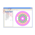
This concept is a little difficult to understand just in words, am going to show you in this column the results obtained from a simple experiment in JMAG-Public. An SPM motor with an outer radius φ80 (mm) and stack length 50 (mm). Compare results between a medium rotor radius of φ40 (mm), a copper machine with a lower rotor radius of φ30 (mm) and an iron machine with a higher radius of φ50 (mm). Changing the rotor radius also changes the magnet amount, so adjust the number of coil turns so the torque doesn't change from 7(A). The result is that although the torque constant remains steady, balance changes with total magnetic flux created by the magnets, coil inductance, copper loss and iron loss.
 Fig. 1 Motor geometry Copper machinery_φ30 (top) and
iron machinery _φ50 (bottom) and
Initial design proposal_φ40 (middle)
Experiment results are shown in Table 1. As expected, copper machines held down iron loss, but conversely copper loss increased. This was because lower total magnetic flux numbers were recovered by the number of turns, whose increase thinned the wire radius and raised resistance by about 40%. Inductance has also increased due to the raised number of turns. The torque constant is steady, so induced voltage is the same but it is possible to predict that the increased inductance raises the number of rotations and makes it harder to turn.
As expected with iron machinery, iron loss increased, but copper loss also increased against expectations. This was because the narrowing of the slot area was accompanied by an increase in the rotor radius and reduction in the number of turns, but despite this the coil needed to become slightly thinner.
Table 1 Design parameters and motor constant
 Fig. 2 Motor parameter sensitivity
If there is a topic you would like us to cover in this column, we will try to deal with it. If you have a theme or opinion regarding content, please contact the JMAG Newsletter Editorial Department.
[JMAG Newsletter January, 2014]