Motor Design Course
Many JMAG Newsletter readers have expressed an interest in motor design, so we decided to do a series on the subject from this issue. But, having said that, we're analyzers and not motor design specialists. That makes it a bit rich to say we're holding a course. Nonetheless, we kick off this series with the thought that it might be useful for readers to pass on what we've learned about motor design through plenty of painful experiences in the past.
Why JMAG is Holding a Motor Design Course
JMAG is a general-purpose electromagnetic field analysis software with a broad array of analysis targets and handling general electromagnetic phenomena like electronic machinery. Many readers probably already know that a lot of our clients use JMAG for motor R&D. That makes the precision of our analysis function development and motor analysis outstanding and many items can be implemented or conducted quickly.
In the past there used to be only a few technicians capable of motor design, and they were especially rare in the area of motor design for electromagnetic field analysis. For that reason, it was a little difficult to expect there would be an easy-to-use simulation software. Richly experienced expert technicians wanted to come up with some way of solving this issue of software that people found difficult to use.
Recently, various types of equipment use motors, so there has been an increase in technicians designing or selecting motors. That has, in turn, raised expectations about deliverance of an easy-to-use software. We obtain valuable information through such ways as the JMAG Technical Support we provide on a daily basis or visiting our customers and talking to them. But, due to matters like classified information concerns, information or demands can be patchy, which prevents gaining a grasp of the overall and many of us are left feeling irritated. We, being in the position of a software producer and service provider, came to believe that we should know how people are using JMAG for designs because no matter what software we made and service provided, or what various types of software we developed or the diversity of information we provided, to know if we were contributing to our customers we also needed to learn about motor design. For example, it's the same sort of thing as an artisan who makes musical instruments who may not be good enough a performer to put on a show, but if they are able to play a little bit they still know more about using musical instruments than an artisan who has never played and thus they can also create a better musical instrument. I don't want to go on about it for too long -- some may say we're already too late to be talking about this topic. But, that's how we came to be seeking to learn more about motor design.
In addition, JMAG Technical Support has also been receiving an increasing number of inquiries about motor design or evaluation and not just about how to use JMAG. A perfect example of this comes with the following case. "When I do an analysis of the voltage, the torque is always negative. Is this a bug?" This was a question we were asked. Ultimately, it wasn't a JMAG bug, but there was a simple reason for why the current was always running into the negative: the set number of rotations was high, which meant induced voltage became greater than supply voltage, but many people hadn't been able to realize that and continued to worry. To help these users feel at ease with JMAG, we thought we should provide them with information about motor design, which in turn inspired us to hold a motor design course where people could learn about the subject.
Textbook Project
For a few years now, JMAG has been thinking about this matter and wanted to hold design workshop seminars for people who intended to do motor design. These were small seminars for four or five people and held for beginners or others who were looking to get into motor design. The lectures' design targets were brushless DC motors and talked about such requirements as motor characteristics, identified main dimensions and went through to give an estimation of functionalities in seminars that attracted many participants. But the seminars only went for half a day, which wasn't long enough to be able to pass on what we wanted to. It was also tough for people to get the time to go through a series of seminars. That led us to think it would be better if we could provide the information in some sort of proper format, such as a textbook or reference manual.
We initially started looking around for an easy textbook accessible to motor design beginners such as ourselves, but could not find anything within Japan. This was possibly because the brushless DC motor itself was a comparatively new field of technology (or, maybe it had something to do with JMAG often being used in the brushless DC motor field).
Consequently, we decided that by arranging into a textbook form the things we were about to learn regarding motor design and associating them with methodologies for JMAG-Express and JMAG-Designer we would be able to contribute to JMAG users and potential users (bearing in mind that we're also a private company operating for profit and could not provide these things on a purely voluntary basis).
Our current concept is to use the textbook as a sub-manual for JMAG-Express and by changing and experimenting with all sorts of design parameters within JMAG-Express teach ourselves the fundamentals of motor design. We have released a video of a motor design using JMAG-Express and posted this online at the link below. Anybody who's interested, please take a look.
JMAG-Express Public Website
With the release of the textbook we would like to obtain feedback so we can use this to improve the contents of the learning manual. Please help us with this and let us know your thoughts on the textbook.
 Fig. 1 JMAG International Top Page
The JMAG-Express page is accessible directly from the JMAG top page, so please check it out.
 Fig. 2 Web video starting scene
A website slideshow gives a step-by-step look at motor design using JMAG-Express. In the initial stage, the sizing function is used to create a rough size, which is one of the benefits of JMAG-Express, which allows for tests of various and diverse proposals.
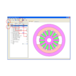
 Fig. 3 Inputting parameters
A JMAG-Express screenshot above changed parameters and written explanations of those changes. The examination process is listed on the right, enabling a crow's nest view of the trial and error process.
 Fig. 4 Analysis results and their analysis
Space is provided below analysis results obtained from JMAG-Express with examples aimed at understanding what the results are and how decisions can be made about these results.
We'll start the design course from the next edition
The first edition of this series was mostly to inform what we will be writing about in the future. During the next Newsletter, we will start the course while using the textbook, so please prepare for that.
At the same time, we will also be releasing information on the website or through videos, so please expect to see these, too.
(Yoshiyuki Sakashita)
Column: Concentrated Winding and Distributed Winding
With the motor design course we plan to give explanations while focusing on individual decisions made during the process of designing a motor. This column will pick up a particular issue about motor design, use JMAG to do a simple verification and then explain what has happened.
In this issue, I'd like to talk about concentrated and distributed winding. A general property of concentrated winding is that the coil is wound directly onto one pole of the teeth, so there is no need to wind the coil around several teeth as is the case with distributed winding. This results in enabling shortening of the coil end height, which both cuts the motor's copper loss and contains the axial direction of the motor itself. In the manufacturing process, these abilities give it benefits like enabling comparatively fewer processes or tools than for distributed winding. On the other hand, one of its weaknesses is an uneven magnetic circuit because the number of stator core teeth for each pole is kept to a minimum. This means a lower rate of magnetic flux that includes many flux linkage harmonic components, which makes it easier for generation of torque fluctuations and simple increases of iron loss, both of which are additional disadvantages.
Consequently, restrictions apply to the outer diameter axial direction dimensions. When trying to limit the height of the coil end, or torque covers a comparatively large area and the motor is in equipment prioritizing reduction of copper loss, concentrated winding is said to be effective.
(Reference materials: Takeda, Yoji, et al, "Interior magnet motor design and control," Ohmsha Ltd.)
First, perform a magnetic field analysis of concentrated winding and distributed winding. Make the analysis model rotor geometry and stack length the same and the drive conditions are also to be identical. All that should differ is the stator geometry and coil resistance (Fig. 1)
Fig. 1 Motor geometry Concentrated winding (left) and distributed winding (right)
An initial comparison of the no-load induced voltage shows a significant difference in waveforms (Fig. 2). Concentrated winding has fundamental wave amplitude almost identical to that of distributed winding, but the fewer slots means a different ratio of higher components that results in expression of different waveforms (Fig. 3).
Fig. 2 No-load induced voltage waveform Concentrated winding (left)
and distributed winding (right)
(Click to enlarge)
Fig. 3 Frequency components of the no-load induced voltage waveform
Concentrated winding (left) and distributed winding (right)
(Click to enlarge)
Looking at the analysis results of a load operation shows a difference in sensitivity in the current position. As stated earlier, the flux path is uneven in concentrated winding and field weakening controls cause reluctance torque (Fig. 4).
Fig. 4 Current phase/Torque properties Concentrated winding (left)
and distributed winding (right)
(Click to enlarge)
Individual dq-axis inductance is listed below:
Concentrated winding: Ld=1.900(mH)/ Lq=2.163(mH)
Distributed winding: Ld=1.412(mH)/ Lq=2.057(mH)
The dq-axis inductance value also shows that we should not have great expectations regarding reluctance torque in concentrated winding.
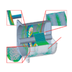
A feature of the analysis loss attained was magnet current eddy loss. Concentrated winding had more significant reverse magnetic field changes than distributed winding, which increased the changes produced in the magnet's eddy current loss (Fig. 5). Heat generated in the concentrated winding magnet was 23.4 (W) compared of 2.6 (W) generated in the distributed winding magnet.
Fig. 5 Eddy current loss of the magnet Concentrated winding (left) and distributed winding (right)
Magnetic loss in itself does not have a great effect on the efficiency of the entire motor, but because heat is generated in the magnet, which is the most easily affected material of all those used in the motor, when actually designing you must take note of decreased performance or demagnetization caused by thermal demagnetization.
Results also showed that rotor iron loss was greater in concentrated winding than it was with distributed winding (Fig. 6). Iron loss values are below.
Concentrated winding: Stator 64.4(W)/Rotor 21.6(W)
Distributed winding: Stator 76.5(W)/Rotor 8.1(W)
* 9000(rpm)/70(Apeak)
Fig. 6 Iron loss distribution contours Concentrated winding (left) and distributed winding (right)
If there is a topic you would like us to cover in this column, by all means please let us know and we will try to deal with it. We are also waiting for any opinion you may have about the details of this column. Contact us using the reference below.
[JMAG Newsletter September, 2013]