Contents
1. Anomalous eddy current loss calculation method in high accuracy iron loss analysis method
2. Verification of high accuracy iron loss analysis method including anomalous eddy current loss
2.1 Evaluation of error at the time of direct current superposition
2.2 Fundamental wave + harmonic Wave evaluation
3. Limits of the method
3.1 Dependence of coefficients
3.2 Physical modeling
4. Conclusion
5. References
Overview
The iron loss analysis method the most commonly applied uses measured iron loss data (hereinafter referred to as the conventional method). In the conventional method, since the application range is limited to the measurement conditions, there were problems in evaluating the influence of harmonics and DC superposition. On the other hand, new models such as play models and 1D methods, have come to be applied to iron loss analysis (hereinafter referred to as new methods). However, even with these new methods they still won’t be able to take in account the anomalous eddy current loss.
The previous report [[W-MA-88] Improvements in Accuracy of Anomalous Eddy Current Loss Calculations (1)] showed a method applicable to transient calculation as a modeling method of anomalous eddy current loss. The challenge of this method, has been a problem of physical interpretation of fitting by a function of anomalous eddy current loss correction coefficient, and a coefficient of less than 1 in a high frequency region. In this paper, as a result of examining and applying a new modeling method of anomalous eddy current loss, it is possible to obtain anomalous eddy current loss according to the excitation state. However, it was found that when applied to a high-frequency, high-DC bias field with large deviation from the excitation state at the time of derivation, it deviates from the actual measurement. It was confirmed that the iron loss due to the waveform including the harmonics can be calculated with high accuracy under the condition that the frequency is 1 kHz or less and the direct current superimposed amount is not large.
1. Anomalous eddy current loss calculation method in high accuracy iron loss analysis method
Anomalous eddy current loss was obtained by separating components from the measured iron loss value in the conventional method. However, in the new method, the anomalous eddy current loss is determined by simulation. A method often used for practical convenience is to consider anomalous eddy current loss as a correction factor for classical eddy current loss [7]. However, the conventional anomalous eddy current loss coefficient identification has the following problems.
- It applies the value identified at low frequency in the entire frequency range.
- Skin effect is not considered in the classical eddy current loss at the time of identification
Therefore, in this white paper, we attempted to improve the anomalous eddy current loss coefficient by the following method:
- Coefficients are identified for each operating point
- At the time of identification, the hysteresis loss is calculated using the play model, and classical eddy current loss is calculated using the 1D method
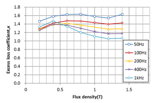
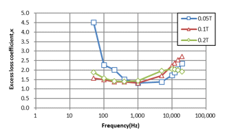
Table 1 shows the improvement of the method, Fig. 1 shows the excitation magnetic flux density amplitude obtained by this method, and the anomalous eddy current loss coefficient for each frequency. It can be observed that it changes with respect to the magnetic flux density and that it changes with increasing frequency after decreasing.
This white paper uses this method to calculate the core loss for a magnetic flux density waveform including harmonics, and reports the results comparing it with actual measurements. We will also explain the application scope of this method.

(a) Magnetic flux density amplitude dependency (frequency 50 Hz-1 kHz)

(b) Frequency dependency (amplitude 0.05 T-0.2 T)
Anomalous eddy current loss coefficient (35A360)
Iron loss is 0.05 to 1.4 T, 50 Hz to 20 kHz the measurement was performed in the range of
You need to sign in as a Regular JMAG Software User (paid user) or JMAG WEB MEMBER (free membership).
By registering as a JMAG WEB MEMBER, you can browse technical materials and other member-only contents for free.
If you are not registered, click the “Create an Account” button.
Create an Account Sign in


