Contents
Overview
1. How to evaluate a coupled control circuit analysis efficiently.
2. The challenges of the proposed method
3. Setting the resolution of the JMAG-RT model
3.1 Motor
3.2 Error of resolution and magnetic flux amount
3.3 Comparison of Calculation Time and Results
4. Summary
5. Reference
Overview
In electrical machine design, the use of coupled analysis between the electromagnetic FEA and the motor drive control circuit is necessary in order to have an understanding of the harmonic iron loss, hysteresis loss, etc. due to the PWM switching [1]. However, the coupling of a transient FEA study with a control circuit can be time consuming.
In this paper, we will propose a method to increase the speed of such studies. The method consist of using a high precision equivalent circuit model of our motor during the early transient state of the control to accelerate the calculation time. Then only once the steady state is reached, the rest of the calculation is done using FEA. When tested we found that using that method you could reduce your calculation time by about ½, assuming that equivalent circuit model’s accuracy is similar enough to the FEA.
1. How to evaluate a coupled control circuit analysis efficiently.
The performance of an electrical machine is generally evaluated in steady state. Since the control circuit coupling implies necessarily a transient component during the simulation, it will require to calculate for a number of electrical cycles before reaching the steady state. Furthermore, in order to capture current waveform due to the PWM, will require a fine time step. Therefore, this requires for each electrical angle period a large amount of steps leading to long calculation times to obtain the results. As a method to reduce the calculation time, the transient response of the control circuit is analyzed using a highly accurate equivalent circuit model of our machine (hereinafter referred to as JMAG-RT model). Once the steady state is reached, the analysis will then switch to FEA calculations.
2. The challenges of the proposed method
With the proposed method, the total calculation time is the sum of the time required to create the JMAG-RT model and the time required for the execution of coupled circuit control analysis. Therefore, this total time needs to be shorter than the conventional computing time. On the other hand, when switching from JMAG-RT model to FEA model, if the JMAG-RT model and the FEA model cannot be matched in linkage flux amount, an electromotive voltage difference occurs and a transient response occurs. Fig. 1 shows a state in which a transient response occurs when the switching calculation is performed.

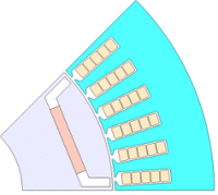
Motor (1/8 part of the whole)

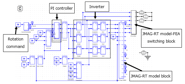
The control circuit model
Operation according to speed command value determine the point and calculate the command value of dq axis current. The dq axis current flowing in the motor is compared with the command value to determine the voltage value applied to each phase coil.
You need to sign in as a Regular JMAG Software User (paid user) or JMAG WEB MEMBER (free membership).
By registering as a JMAG WEB MEMBER, you can browse technical materials and other member-only contents for free.
If you are not registered, click the “Create an Account” button.
Create an Account Sign in


