Contents
1. Introduction
2. Mesh Resolution for Accurate Calculation of Coil AC Loss
3. Conclusion
4. References
1. Introduction
In recent years, the use of square wire coils has been on the rise to produce higher output in rotating machines. For this reason, in analysis, there has been an increase in modeling wire geometries for the calculation of eddy currents and AC losses in the wire. In order to calculate AC losses in the wire, it is necessary to accurately capture interlinking flux as well as the skin effect and proximity effect produced by it. In mesh division, a sufficient resolution is sought to capture these phenomena. However, if the resolution is increased too much, the scale of the model becomes excessively large. This leads to an increase in calculation cost, so it becomes necessary to set an appropriate resolution.
In this report, coil AC loss analysis is examined from the perspective of mesh modeling.
2. Mesh Resolution for Accurate Calculation of Coil AC Loss
Three phenomena can be thought to cause AC losses in the coils of rotating machines.
- Eddy current caused by the leakage flux from the core.
- Harmonic components included in the current waveform causing the skin effect in wires as well as biases in loss density distribution.
- The proximity effect caused by eddy currents due to magnetic flux from other wires.
Leakage magnetic flux generated inside the slot is complex, and how leakage flux occurs depends on the shapes of the teeth and on magnetic saturation. Also, unlike transformers and reactors, the direction of leakage magnetic flux also fluctuates with rotation, so it is not necessarily interlinking fixed regions. In order to set an effective mesh resolution for general purposes, it is useful to conduct analysis without considering eddy current beforehand and confirm the regions where leakage magnetic fluxes interlink. If eddy currents are taken into account in the analysis prior to this one, the magnetic flux obtained includes the influence of the demagnetizing fields caused by the eddy currents, and the magnetic flux component interlinking the wires cannot be evaluated correctly.

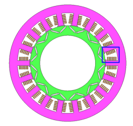
(a) Entire model

(b) Wire expansion
Fig. 1 Coil AC loss analysis model
Model the wire geometry, set the FEM conductor, and calculate the eddy current
You need to sign in as a Regular JMAG Software User (paid user) or JMAG WEB MEMBER (free membership).
By registering as a JMAG WEB MEMBER, you can browse technical materials and other member-only contents for free.
If you are not registered, click the “Create an Account” button.
Create an Account Sign in


