Contents
1. Background
2. Differences between 2D and 3D models seen in motor characteristics
3. 3D correction and its limitations
4. Conclusion
1. Background
A highly accurate plant model is indispensable for model-based design motor drive simulation. By using JMAG-RT or other such software, it is possible to generate a highly accurate plant model from an electromagnetic field FEA model. However, the plant model used in model-based design requires accuracy comparable to an actual machine. This is a level different from the accuracy required for FEA in motor design.
Meanwhile, in automobile drive motors and other such motors, rotating machines are becoming thinner because of high power density and miniaturization. As a result, the approximations from 2D models which have been conventionally used in electromagnetic field analysis of rotating machines are not sufficiently accurate. This also affects the accuracy of plant models.
In this paper, the necessity of 3D FEA models in plant model generation will be discussed.
2. Differences between 2D and 3D models seen in motor characteristics
Here, the differences in motor characteristics in thin motors are looked at. Fig. 1 and Table 1 show the target motor specifications. 2D and 3D FEA models are prepared and their characteristics are compared.
Fig. 2 shows the inductance maps. It can be seen that the inductances are higher in the 3D model than in the 2D model. This is because the coil ends are modeled in the 3D model and the inductance of the end portions is taken into account.
Fig. 3 shows the torque maps. In the region where the current amplitude is high, the 2D model shows higher torque compared to the 3D model. This is because in the 2D model, even during magnetic saturation the magnetic flux does not leak in the axial direction causing the torque contribution to be high. Whereas in the three-dimensional model, the effect of leakage magnetic flux due to magnetic saturation can be taken into account.
Fig. 4 shows the NT characteristics. It can be seen that the curves are different between the 2D and 3D models. In the low speed high torque region there is magnetic saturation and the differences in the torque maps are exhibited in the NT characteristics. On the other hand, there is no magnetic saturation in the field weakening region, but since the inductance is high in the 3D model the current decreases, and as a result the torque is lower than in the 2D model. Even with the same motor, it can be confirmed that the motor characteristics change when incorporating the effects from 3D modeling. The importance of the 3D FEA model can be understood with regard to the accuracy requirements of a plant model comparable to an actual machine.
When using a 3D FEA model to generate a plant model, long generation times are a problem. In contrast to this, it is possible to shorten generation times by distributing and executing FEA at each operating point. Fig. 5 shows the result of shortening the generation time by distributing jobs when generating a plant model from a 3D FEA model.
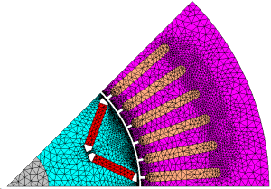
(a) 2D model
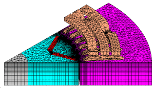
(b) 3D model
Fig. 1 IPM motor
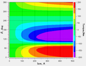
(a) 2D
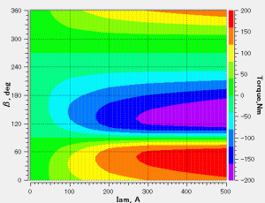
(b) 3D
Fig. 3 Torque maps
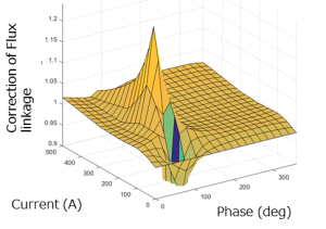
(a) Flux linkage correction factors
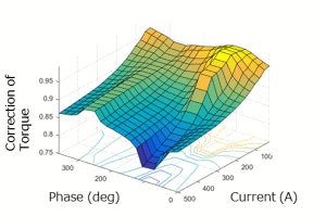
(b) Torque correction factors
Fig. 6 Correction factors
The correction factor distributions are complex with respect to the current amplitude and the phase.
You need to sign in as a Regular JMAG Software User (paid user) or JMAG WEB MEMBER (free membership).
By registering as a JMAG WEB MEMBER, you can browse technical materials and other member-only contents for free.
If you are not registered, click the “Create an Account” button.
Create an Account Sign in


