Contents
1. Introduction
2. Issues during the estimation of the vibration by analysis
3. Correlation analysis in order to solve problems
4. Details of correlation analysis
5. Example of correlation analysis
5.1 Specifications of the motor model
5.2 Natural frequency measurement
5.3 Modeling stator core
5.4 Modeling with coil added to the stator core
5.5 Creating stator core, coil, and frame in one model
5.6 Assembly Modeling
6. Summary
7. References
1. Introduction
In recent years, control of the vibrations has been an important subject for manufacturers in designing electrical equipment. Though electric motors used in electric vehicles are generally quieter than engines, vibration and noise are sometimes problematic because of their wide operating range. In addition, regulations on vibration and noise are becoming stricter, especially when installing large transformers in locations near residential areas.
For this reason, electromagnetic vibration simulations are also being carried out extensively in the field of simulations, and they are being fully utilized in designing electrical equipment. Vibration and noise are generated by structure resonating and amplifying with an electromagnetic vibration becoming a vibration source. When CAE is utilized in reducing the vibration and noise, the distribution and temporal change of EM force are determined from electromagnetic field analysis, and the obtained results are used as inputs in conducting vibration and noise analysis in order to evaluate whether an electric motor structure generates harmful vibration and noise or not. If vibration can be estimated with high accuracy, the cost of prototype and testing can be reduced, and thus the reduction of the overall product development time is achievable.
2. Issues during the estimation of the vibration by analysis
As a pre-existing problem of electromagnetic vibration simulation, there is often a case in which the actual measurement and simulation results do not match. This makes it impossible to utilize simulations for designing and to reduce the number of prototypes and tests.
As mentioned earlier, the vibration becomes large with the superposition of the exciting force and the natural mode. In other words, it is necessary to accurately comprehend both the exciting force and the natural mode in order to achieve high accuracy in the estimation of the vibration. Here, we focus on improving the accuracy of the natural mode as we already know from our previous experience that high accuracy is obtained for the exciting force in many cases. Factors and measures for having natural mode mismatch are described below with the case of a motor as an example.
First, the effect of the core’s laminated structure on the stiffness is considered one of the factors. In the case of a laminated core, the in-plane direction is always an iron, however, the stacking direction is alternately stacked with an iron and an insulating layer. Therefore, the stiffness is anisotropic in both in-plane and stacking directions, however, since the part is being modeled as one piece, and given an isotropic stiffness, there are many cases where the simulation result does not match that of the measured data. As a countermeasure, the core’s laminated structure should be modeled accurately.
Second, the effect of simplifying the structure of the winding is considered as one of the factors. The coil is primarily in a condition where the wire is bundled, and detailed modeling has not been done in many cases, because of the insulating coating. In order to accurately represent the condition, it is necessary to physically model the winding and the insulating coating and to account for the contact and friction for both entities.
The effect of modeling not just a single part, but also the connection, contact, and friction between parts is also considered as one of the factors. Between the rotor core and the magnet, and between the stator core and the case are not primarily rigidly connected, and include the effect of the adhesive layer, contacting state, and friction. As rigid connections result in higher stiffness, adhesive layer, contacting state and friction must be accurately modeled.
Nevertheless, modeling all physical phenomena is likely to increase the magnitude of the model. There are also technical challenges, which make the above method unrealistic, such as what kind of measurements are necessary in order to understand the state of contact, friction, and connection in the actual machine as well as on how to apply the conditions to the analysis model.
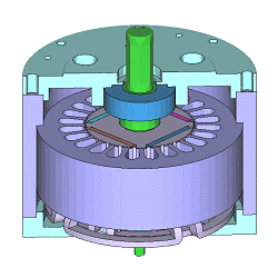
Analysis model (permanent magnet synchronous motor, PMSM)
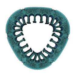
5th mode shape of stator core
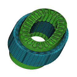
1st mode shape of stator core and coil
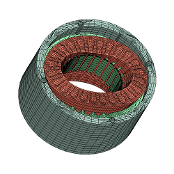
2nd mode shape of stator
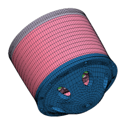
3rd mode shape of assembly
You need to sign in as a Regular JMAG Software User (paid user) or JMAG WEB MEMBER (free membership).
By registering as a JMAG WEB MEMBER, you can browse technical materials and other member-only contents for free.
If you are not registered, click the “Create an Account” button.
Create an Account Sign in


