Overview

Solenoid valves are often used for hydraulic valves and injectors, and the movable part itself is placed in high pressure liquid and encounters flow resistance. Since the movable part uses a guide to move, there is error with the possibility to cause an inclination. In the case of inclination, the electromagnetic attraction force is unbalanced, so it is necessary to confirm beforehand whether or the force acts in the proper direction.
It is useful to examine by FEA beforehand whether there is a change in the attractive force when there is an inclination and whether an unbalanced force causes the movable part to become unaligned.
In this example, an example is presented where the influence on the electromagnetic force by the presence or absence of inclination is confirmed at each position of the movable part.
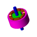
Position and Inclination of The Movable Part

Influence on Electromagnetic Force
Fig. 2 shows the attractive force from the inclination at each movable part position, and Fig. 3 shows the torque around the center axis of the inclination.
As can be seen in Fig. 2, the inclination has almost no affect on the attractive force at the gap length of 3.6 mm, but the attractive force increases by 20% without inclination compared with inclination at 1.9 mm, and decreases by 3% at 0.2 mm.
As shown in Fig. 3, with inclination it can be seen that the torque becomes larger as the gap length becomes shorter. In this example, since the positive direction of the torque and the direction of the center axis of inclination are made to coincide with each other, it is seen that the unbalanced force generated in the movable part acts in a direction to increase the inclination.


Electromagnetic Force Distribution
Fig. 4 to Fig. 6 show the electromagnetic force distribution around the movable part at each position.
As shown in Fig. 4, at the gap length of 3.6 mm almost no change in electromagnetic force due to inclination is observed. On the other hand as shown in Fig. 5, it can be seen that the electromagnetic force increases at the position where the fixed iron core and movable iron core are closest with an inclination at the gap length of 1.9 mm. As a result, the attractive force has increased. With the gap length of 0.2 mm shown in Fig. 6, the electromagnetic force acts not only in the motion direction but in the horizontal direction due to the inclination of the movable part. It can be seen that this is the reason for the decrease in the attractive force.