
Please enter your username and password to sign in.
* A JMAG Software User (paid user) account is required.
*It is different from the service for JMAG WEB MEMBER (free membership). Please be careful.
Overview
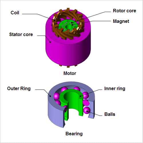
Motors driven by PWM inverters are widely used in household appliances. It is known that when a PWM inverter is used for drive, common mode current flows and axial voltage is produced in the motor's bearings. Electric corrosion is caused in the bearings by this axial voltage, which can reduce the motor's reliability and life.
It is advantageous to use analysis to grasp the stray capacitance in advance, because the common mode current is produced by stray capacitance acting parasitically on the motor's parts.
This note presents the use of analysis to obtain the stray capacitance between an IPM motor's coil and stator core, between its rotor core and stator core, and between the inner and outer rings of its bearings.
It is advantageous to use analysis to grasp the stray capacitance in advance, because the common mode current is produced by stray capacitance acting parasitically on the motor's parts.
This note presents the use of analysis to obtain the stray capacitance between an IPM motor's coil and stator core, between its rotor core and stator core, and between the inner and outer rings of its bearings.
Electric Field Distribution
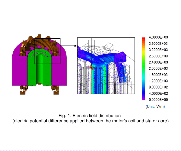
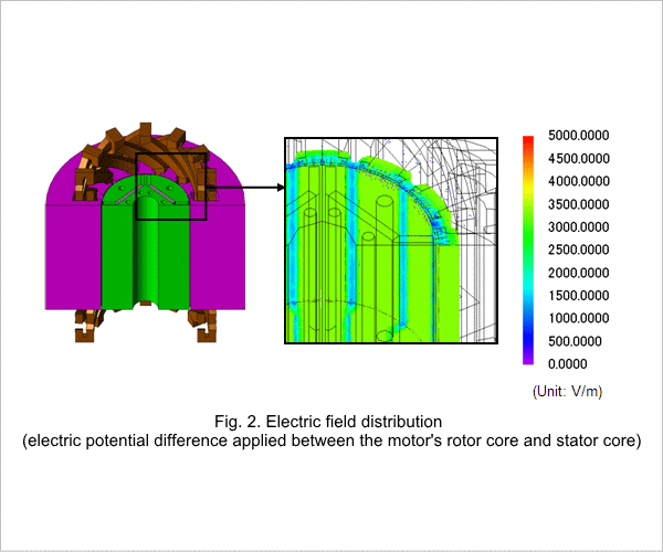
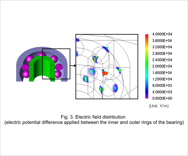
The electric field distribution when the electric potential difference is applied between the motor's coil and stator core, the motor's rotor core and stator core, and the inner and outer rings of the bearing are indicated in figures 1, 2, and 3. A large electric field is produced: in the air in the slots near the coil and stator core when the electric potential difference is applied between the coil and stator core; in the air in the gap when the electric potential difference is applied between the rotor core and the stator core; and through the balls, which are conductors, when the electric potential difference is applied between the inner and outer rings.
Stray Capacitance
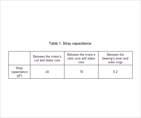
The stray capacitance between the motor's coil and stator core, between the motor's rotor core and stator core, and between the inner and outer rings of the bearings is indicated in table 1. Axial voltage is produced by the stray capacitance.