Overview
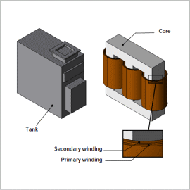
Predicting these losses and the heat that they generate is a vital component of transformer design, but it is difficult to estimate them from desktop calculations, so evaluations and detailed analyses using the finite element method (FEM) are indispensible.
This Application Note explains how to obtain losses in a transformer tank and use them to evaluate the temperature distribution in each part.
Joule Loss Density Distribution
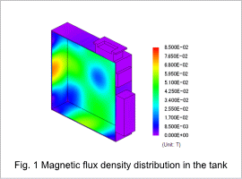
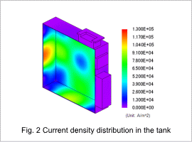
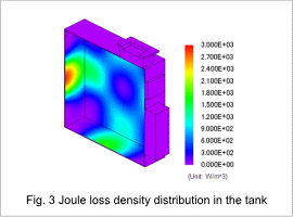
Fig. 1 shows the magnetic flux density distribution, fig. 2 shows the current density distribution, and fig. 3 shows the joule loss density distribution in the tank. From fig. 1, it is apparent that magnetic flux is leaking from the transformer to the tank. This leakage flux generates eddy currents in the tank, as shown in fig. 2. Fig. 3 shows that joule losses get bigger in places with high current density.
Iron Loss Density Distribution
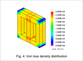
Losses
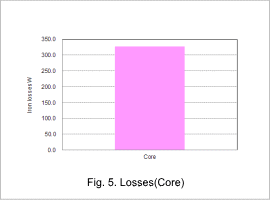
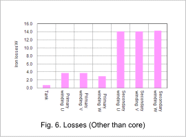
Fig. 5 and Fig. 6 shows the losses in each part. Use these loss values as heat sources to run the thermal analysis.
Temperature Distribution
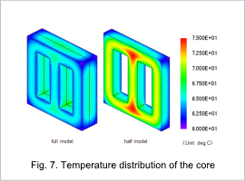
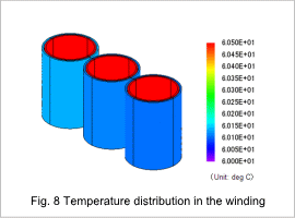
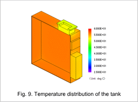
Fig. 7 shows the core’s temperature distribution, fig. 8 shows the winding’s temperature distribution, and fig. 9 shows the tank’s temperature distribution. From fig. 7, it is apparent that the temperature in the outside of the core is lower than in the inside of the core. This is because the core is cooled by insulating oil. In the same way, from fig. 8 it is apparent that the primary winding on the outside has a lower temperature than the secondary coil on the inside. From fig. 9, it is apparent that the temperature of the tank has not risen higher than the temperature of the insulating oil.
