Overview
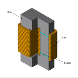
By setting gaps in the core of the reactor, it becomes difficult for the core to become magnetically saturated making a stable inductance obtainable. However, the position of the air gaps may affect Joule loss and eddy currents in the coil.
Therefore the position of the air gaps is an important issue in the design of a reactor. It takes however an inordinate amount of time and much cost to perform studies in trial production. By using FEA, it is easy to visualize leakage magnetic flux and compare Joule losses against air gap positions easily.
In this example, investigating Joule loss with respect to the positions of air gaps in a reactor is presented.
Flux Leakage
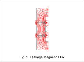
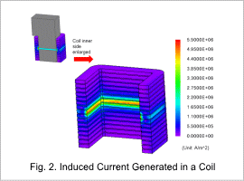
A sine wave current of 0.5 A at 10 kHz is supplied to the reactor. If there are spacers (air gaps), there is leakage magnetic flux. In addition, this leakage magnetic flux induces current in the coil, generating Joule loss.
The leakage magnetic flux in a certain area is shown in Fig. 1, and the induced current generated in the coil is shown in Fig. 2.
Joule Losses Comparison
Next, losses are compared when changing the spacer positions over 19 intervals.
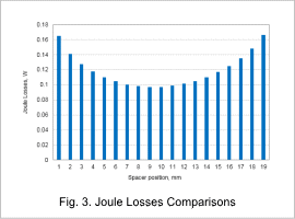
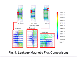
Fig. 3 shows a Joule loss comparison graph and Fig. 4 shows leakage magnetic flux comparisons.
From Fig. 3 it can be seen that the position of the spacers greatly affects the Joule loss in the coil.
When the two spacers are placed side by side, some of the magnetic flux leaks from the core center.
As shown in Fig. 4a, when the two spacers are placed close to each other, it is seen that the magnetic flux leaks to the sides, is short-circuited, and flows near the core center. In addition, as shown in Fig. 4b, if spacers are placed at the mid-interval position from the center, though leakage magnetic flux is generated, it can be seen that it is over a smaller region. However in Fig. 4c it can be seen that the leakage magnetic flux extends to the nearby portion of the core as with the magnetic flux short-circuit portion of the core in Fig. 4a.
