Overview
In order for a solenoid valve to function well, it is necessary to improve control signal responsiveness. To this end, it is necessary to shorten the displacement time of the mover. However, since the degree of freedom in the structure of a solenoid valve can be increased, there is a demand to minimize the volume of the solenoid valve. In order to satisfy these conditions, applying automatic processing using an FEA optimization function can greatly reduce man-hours.
In this example, an example where the geometry of a solenoid valve is optimized using a multi-objective optimization algorithm is presented.
Optimization Conditions
The mover displacement time is the measured time from when the coil is energized until the mover reaches its final position. Therefore, the influence of the mover geometry on the displacement time is focused on.
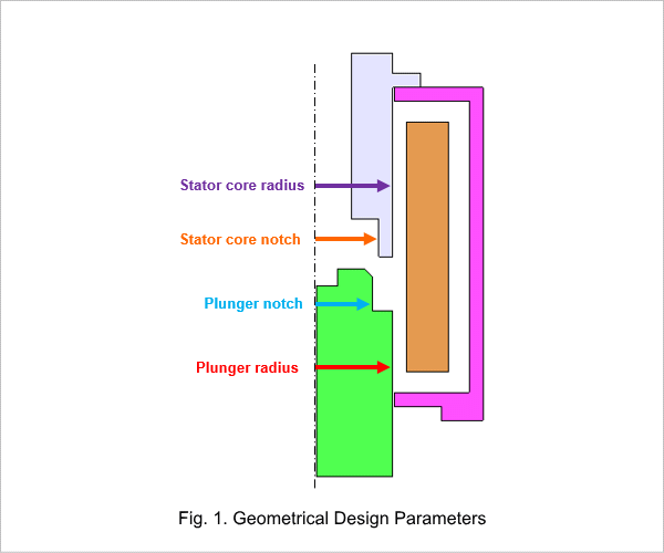
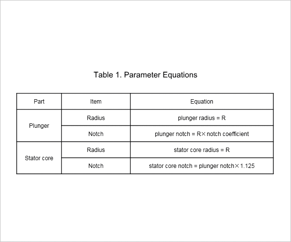
Fig. 1 shows the geometry parameters which are variables. Geometry parameters for optimization can be represented by two parameters, the radius and a notch coefficient. Table 1 shows equations for parameters showing the relationship between geometry parameters.
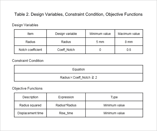
In this example there is a trade-off in that the volume becomes large when the mover displacement time is short and the mover displacement time becomes long if the volume is small. Optimization is performed to shorten the displacement time and minimize the volume. Table 2 shows the optimization design variables, a constraint condition, and the objective functions.
Displacement time and volume
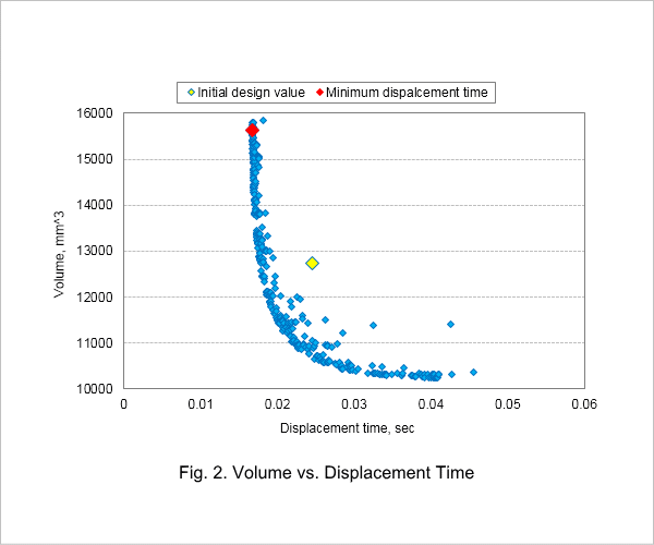
It can be seen that increasing the radius thus the volume shortens the time for the mover to reach its final position. The minimum displacement time is 16.8 msec, for which the radius is 7.9 mm and the volume is 15,621 mm^3.
The case for the initial design values is indicated by a yellow marker, and the case for the minimum displacement time is indicated by a red marker. Comparing the case for the minimum displacement time with the case for the initial design, for the minimum displacement time case the displacement time decreases by 32% but the volume increases by 23%.
Volume times displacement time vs. radius
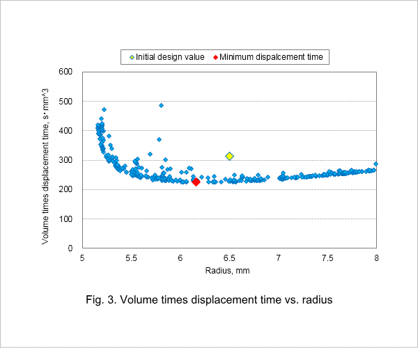
The case for the initial design values is indicated by a yellow marker, and the case for the minimum displacement time is indicated by a red marker. In Fig. 3 it can be seen that the optimized values are 224 s·mm^3 for volume times displacement time and 6.16 mm for the radius. In this case, the volume decreases by 5% from the initial design and the volume times displacement time decreases by 28%. This shows that the displacement time for a given volume improves.

