Overview
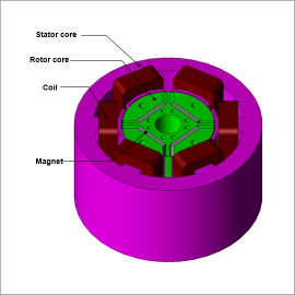
Although it is difficult to understand the temperatures of each part in a real machine, the temperature distribution of each of these parts can be obtained with ease through simulations, and changes to characteristics due to increases in temperature can also be accounted for.
In this example, magnetic field and thermal coupled analysis is run, and changes in torque due to part temperatures and magnet demagnetization are checked.
Changes in Temperature, Average Temperature, Copper Loss, Temperature Distribution
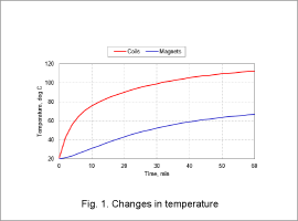
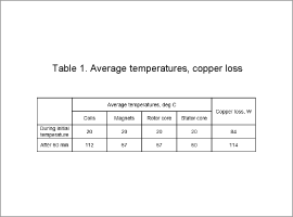
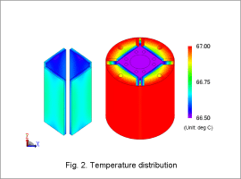
Fig. 1 shows the changes in average temperature of the coils and magnets. Table 1 shows the average temperatures and copper loss for each part during both the initial temperature and after 60 min, and Fig. 2 shows the temperature distribution of the rotor after 60 min.
From Fig. 1 and Table 1, it can be seen that the average coil temperature is highest after 60 min. In this example, the permissible temperature of the coils is 130 deg C. The temperature of the coils is therefore kept below the permissible temperature of 130 deg C. In addition, the copper loss increases after 60 min compared to the initial temperature. In this analysis, because the motor is driven with a specified current, there are no changes in current due to temperature. Copper loss also increases due to the increase in electrical resistance of the coils that occurs because of the increase in temperature.
From Fig. 2, it can be seen that although the inner diameter side of the rotor has a relatively low temperature, the temperature of the magnets is almost uniform. The lower temperature on the inner diameter side is thought to be be caused by the heat that escapes to the outside air through the shaft and housing in the rotor radial direction.
Magnet Operating Points, Torque Waveforms
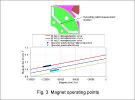
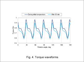
Fig. 3 shows the operating points of the magnets during both the initial temperature and after 60 min, and Fig. 4 shows the torque waveforms during both the initial temperature and after 60 min.
From Fig. 3, it can be seen that after 60 min, the magnets undergo thermal demagnetization, and the operating points change from the initial temperature.
From Fig. 4, it can be seen that torque decreases after 60 min compared to the initial temperature. As mentioned previously, there are no changes in current due to temperature. Therefore, the decrease in torque is due to the thermal demagnetization of the magnets.
