Overview
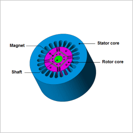
The total amount of these losses is not a dominant factor, but they can be a hindrance when trying to raise efficiency, so they need to be eliminated in the design process. In order to study these problems, both the motor’s electromagnetic behavior and what kinds of controls the drive circuit performs have to be investigated.
In order to run an advance study of these phenomena in CAE, a high fidelity motor model and inverter model need to be coupled. There are three ways of accomplishing this: Directly linking with a circuit/control simulator, entering a current waveform obtained by using a JMAG-RT motor model and a circuit/control simulator, and entering actual current measurements.
In this analysis, the iron losses of the IPM motor that accounts for the carrier harmonic are obtained by directly linking to a circuit/control simulator.
Iron Losses
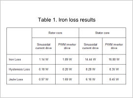
The iron losses in both the rotor core and the stator core increase when the IPM motor is run using a PWM inverter. The joule losses increase the most severely, increasing 70% in the rotor core, and 40% in the stator core.
Joule Loss
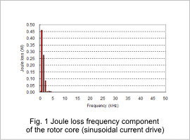
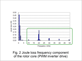
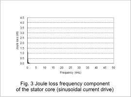
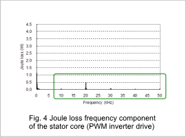
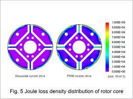
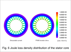
The frequency components of the joule losses are indicated in figures 1 through 4. The joule loss density distribution is indicated in figures 5 and 6.
The fundamental frequency and harmonic component have almost the same amount of iron losses in both the rotor core and the stator core if a sinusoidal current or a PWM inverter is used with a fundamental frequency of 360 Hz for the rotor core and 60 Hz stator core. However, losses are only generated when the PWM inverter is used with a PWM fundamental frequency of 10 kHz and its harmonic component. (These values are indicated inside the green square in fig. 1.)
The increased joule losses when the motor is run using a PWM inverter are caused by the carrier harmonic. The effects of a carrier harmonic need to be accounted for to analyze the characteristics of an IPM motor in detail.
