Overview
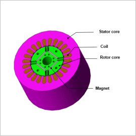
There are three methods to gain an understanding of iron loss that accounts for PWM carrier harmonics: There is the method of linking a control / circuit simulator that contains the PWM inverter with a magnetic field analysis by inputting the current waveform obtained from the simulation into the analysis, the method of inputting the actual measurements of a current into a magnetic field analysis, and the method of inputting the estimated harmonic current.
This Application Note demonstrates a case study where the effects of a carrier harmonic against an IPM motor’s iron loss is confirmed using estimated harmonic current waveform as input.
Iron Loss
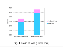
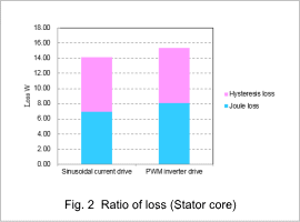
A comparison of the hysteresis losses, and joule losses when the IPM motor is driven by a PWM inverter and a sinusoidal current are shown in fig 1 and Fig. 2.
The iron losses in both the rotor core and the stator core increase when the IPM motor is run using a PWM inverter. The joule losses increase the most severely, increasing 70% in the rotor core, and 20% in the stator core.
Joule Loss/ Joule Loss Density Distribution
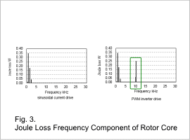
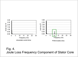
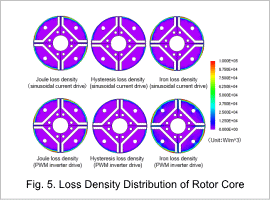
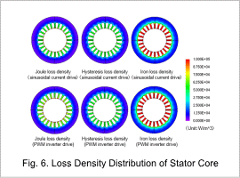
The joule loss frequency components are shown in Fig. 3 and Fig. 4, and the joule loss density distribution is shown in Fig. 5 and Fig. 6.
The fundamental frequencies (360 Hz in the rotor core and 60 Hz in the stator core) and harmonic components have almost the same amounts of iron loss in the rotor core and stator core whether a sinusoidal current drive or a PWM inverter drive is used. However, iron loss is only produced during PWM inverter drive for the PWM‘s fundamental frequency (10 kHz). (These values are indicated inside the green square in the Fig. 3 and Fig. 4.)
The increased joule losses when the motor is run using a PWM inverter are caused by the carrier harmonic.
The effects of a carrier harmonic need to be evaluated to analysis the characteristics of an IPM motor in detail.
